
Bedside Lamp Timers
This circuit design employs a relay to control the power to a lamp, making it suitable for applications where automatic shut-off is desired. The pushbutton P1 serves as the primary control for initiating the timing sequence, while P2 provides a manual override to turn off the lamp at any time. The use of two integrated circuits (ICs) facilitates the timing and blinking functionality. IC2 is responsible for generating the timing sequence through an internal oscillator, which is set to oscillate at a frequency determined by the external resistor and capacitor values. The output from IC2 pin 3 serves as the control signal for the relay, effectively toggling the power to the lamp.
The blinking LED serves as a visual indicator of the remaining time, providing the user with feedback that the lamp will soon turn off. The unique blinking pattern is designed to alert the user without being overly distracting, making it ideal for a nighttime reading environment. The design also allows for the integration of a piezo sounder, which can provide an audible alert in addition to the visual indicator, enhancing user awareness as the time limit approaches.
The circuit is designed to minimize power consumption when the lamp is off, as the ALL-ON ALL-OFF configuration ensures that the system draws minimal current in its idle state. This feature is particularly important for battery-operated devices, as it extends the operational lifespan between charges or replacements. The flexibility in timing adjustments through the modification of R4 and C4 allows for customization according to user preferences or specific application requirements. Overall, this circuit represents a practical solution for automating lamp control in a bedside reading scenario.The purpose of this circuit is that of power a lamp or other apparatus for a given time (30 minutes in this case), and then to turn it off. It`s useful when reading at bed by night, turning off the bedside lamp automatically in case the reader falls asleep.
After turn-on by P1 pushbutton, an LED lights for c25 minutes, but 6 minutes before the tur n-off, start blinking for two minutes, then stop blinking for other two minutes and finally blinks for other two minutes, thus signaling that the on-time is ending. If the user want to prolong the reading, can earn another half-hour of light by pushing on P1. Turning-off the lamp at user`s ease is obtained pushing on P2. Q1 and Q2 forms an ALL-ON ALL-OFF circuit that in the off state draw no significant current. P1 starts the circuit, the relay is turned on and the two ICs are powered. The lamp is powered by the relay switch, and IC2 is reset with a positive voltage at pin 12. IC2 start oscillating at a frequency settled by R4 and C4. With the values shown pin 3 goes high after c30 minutes, turning off the circuit via C3. During the c6 minutes preceding turn-off, the LED does a blinking action by connections of IC1 to pins 1, 2 & 15 of IC2.
Blinking frequency is provided by IC2 oscillator at pin 9. The two gates of IC1 are in parallel to source an higher current. If needed, a piezo sounder can be connected at pins 1 & 14 of IC1. Changing IC2 brand name, varies the oscillation frequency. In particular Motorola`s ICs run faster. Obviously, time can be varied changing C4 and R4 values. 🔗 External reference
Related Circuits
Flashing frequency can be varied by changing R1 value in the 1M - 4M7 range. This circuit is very efficient when driving a small 3.2V incandescent lamp. In this case omit the LED and R3, connecting the bulb across...
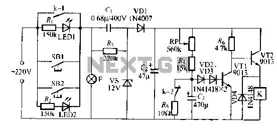
The lamp relay delay circuit is illustrated in Figure 7. Components S131 and SB2 are light buttons mounted in different locations. The lamp can operate with F. LEDs (LED1 and LED2) should be installed in SB1 and SB2 to...

This simple circuit, as shown in the schematic diagram, activates a switch using sound. It can be utilized for various applications, such as automatic sound-controlled disco lights or a car's LED light show. The transistor Q1 amplifies the audio...

A school drama required lamps that automatically turned on and off in sync with the spotlights. The lamp switching system needed to be wireless, durable, reliable, simple, and cost-effective. With the stage and spotlights turned off, minimal light reaches...
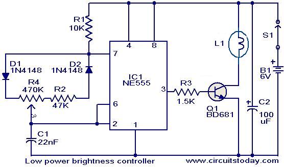
The circuit presented here is designed to control the brightness of low-power incandescent lamps. It utilizes the NE555 integrated circuit, configured as an astable multivibrator with a variable duty cycle. The output from the IC is connected to the...

This simple circuit can be used to flash incandescent lamps with a power rating of up to 10W. The circuit is ideal for creating flashing beacons on automobiles and similar applications. It consists of an astable multivibrator based on...
Warning: include(partials/cookie-banner.php): Failed to open stream: Permission denied in /var/www/html/nextgr/view-circuit.php on line 713
Warning: include(): Failed opening 'partials/cookie-banner.php' for inclusion (include_path='.:/usr/share/php') in /var/www/html/nextgr/view-circuit.php on line 713