
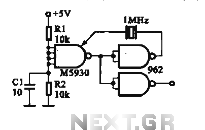
Crystal oscillator DTL integrated circuit
The crystal oscillator circuit operates by utilizing the piezoelectric properties of a quartz crystal, which provides a stable frequency reference. In this design, the DTL integrated circuit plays a crucial role in generating the oscillation signal. The DTL technology is known for its high-speed operation and low power consumption, making it suitable for applications requiring reliable frequency generation.
The circuit is typically configured with a feedback loop that connects the output of the gate circuit back to its input through the crystal. This feedback ensures that the oscillation is sustained at the desired frequency. The choice of oscillation frequencies, such as 100 kHz and 1 MHz, allows the oscillator to be used in various applications, including clock generation for digital circuits, frequency modulation, and signal processing tasks.
The gate circuit within the DTL integrated circuit consists of a combination of diodes and transistors that work together to create the necessary conditions for oscillation. The diodes provide the necessary biasing for the transistors, which amplify the signal and maintain the oscillation. The output signal can be further processed or used directly in the application, depending on the requirements.
Overall, this crystal oscillator design exemplifies the integration of DTL technology with crystal oscillation principles, resulting in a compact and efficient frequency generation solution.By a crystal oscillator b DTL integrated circuit constituted DTL is shown by the crystal oscillator integrated circuits, and the oscillation frequency is 100 kHz and 1 MHz. It is constituted by a gate circuit to provide a signal for the oscillator circuitry DTL.
Related Circuits
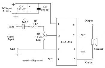
This is an audio amplifier circuit that uses the TDA7052 as the main component, along with five additional components to support its operation. The ideal supply voltage for this circuit is approximately 6-12V, and it does not require a...
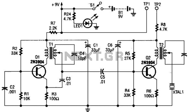
The transmitter features a VXO circuit that drives a keyed amplifier. This keyed amplifier powers an MRF 476 final amplifier, producing approximately 2 watts of output. Additionally, a solid-state T-R switch is incorporated for the receiver. The component values...
The technical parameters of high-speed optocouplers include a rise time (t1) of less than or equal to 300 ns, a circuit transfer ratio (CTR) of 50%, an isolation voltage (VSO) of at least 15,000 V, and an output transistor...

The Saver V5.0 operates a simple clock emulation program that controls a night light to turn on and off at preset times, specifically from 19:00 to 22:00 daily. This design is characterized by its low cost, easy installation, lack...
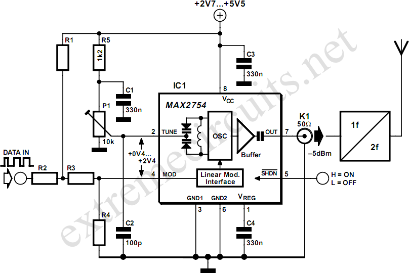
High-frequency voltage-controlled oscillators (VCOs) are challenging to construct, which is why Maxim has developed the integrated 1.2 GHz oscillator, the MAX2754. The center frequency is adjustable via the TUNE input, while a linear modulation input allows for frequency modulation....
This document presents a collection of engaging and challenging electronic circuits that can be built for enjoyment. The author has a long-standing passion for electronics, having studied the subject since middle school and developed numerous circuits over the years....