
Bell Timer Circuit using AT89S52
The bell timer circuit is designed to provide a versatile solution for managing timed alerts in various applications such as alarm systems and educational institutions. The core of the system is the AT89S52 microcontroller, which is responsible for processing user inputs, managing the real-time clock, and controlling the output to the relay that activates the bell.
The integration of the I2C EEPROM allows for the storage of up to 25 distinct alarm timings, enhancing the functionality of the timer. This memory component ensures that the settings are retained even when the power is turned off, providing reliability in the system's operation. The use of the DS1307 real-time clock chip enables accurate timekeeping, allowing the user to set precise timings for the alarms.
To facilitate user interaction, a 4x3 keypad is implemented for inputting the desired alarm times and for configuring the real-time clock. This keypad interface is essential for ensuring ease of use, allowing users to navigate through options and set parameters without complexity.
The LCD display replaces the traditional 7-segment display, offering improved readability and the ability to display more information at once, such as the current time and the status of the alarms. This visual feedback is crucial for users to monitor the system effectively.
The ULN2003 is a key component in driving the relay, which ultimately controls the bell. This relay acts as a switch that activates the bell when the specified alarm time is reached. The ULN2003 is a Darlington transistor array that provides the necessary current amplification to drive the relay coil, ensuring reliable operation.
Overall, this bell timer circuit combines modern components and user-friendly interfaces to create a robust solution for timed alert systems, making it suitable for various applications. The schematic diagram associated with this project would illustrate the connections between these components, providing a clear reference for assembly and troubleshooting.The circuit is bell timer. This new project uses AT89S52 microcontroller and I2C EEPROM to store the alarm timings. Also the 7segment display is replaced with LCD display. DS1307 is used for Real time clock. The user can store upto 25 bell timings and they can even set the time delay for bell ringing in seconds. An 4G—3 keypad is used to enter t he real time clock and the bell timings. ULN2003 is used to drive the relay for the bell. this circuit can used by alarm timer, school bell, etc. Here is a schematic drawing: 🔗 External reference
Related Circuits
The following circuit illustrates the circuit diagram of a motor control unit. This circuit is based on the LM317 integrated circuit (IC). Features include diodes that protect the regulator. The motor control unit circuit utilizes the LM317 voltage regulator to...
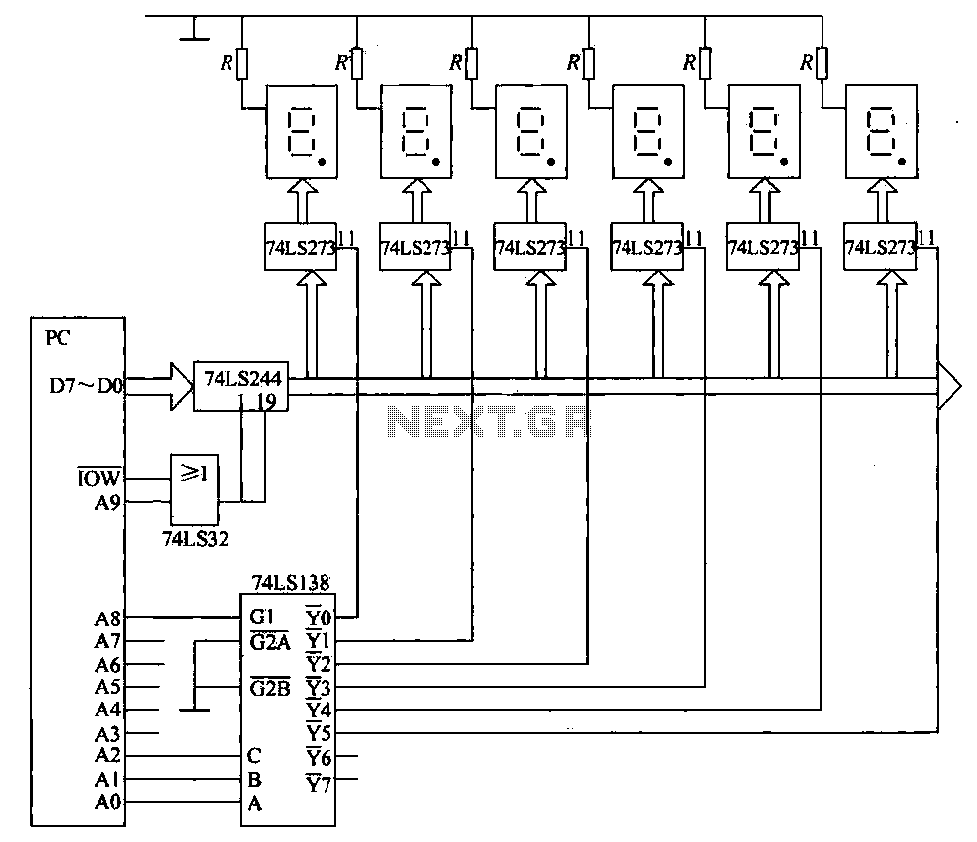
The static display circuit is illustrated in Figure 6. The 74LS244 acts as bus drivers, and six figures represent a public bus, each equipped with an LED display latch (like the 74LS273) connected to the code for latching the...

This is a Variable Voltage Regulator Circuit built using the LM317T integrated circuit (IC). The LM317T is an adjustable three-terminal positive voltage regulator capable of supplying more than 1.5 amps over an output range of 1.25 to 37 volts....
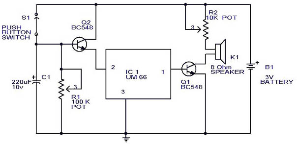
This circuit is a slight modification of a previous design. In the earlier version, the switch needed to be held down for the entire duration of the music playback. In this updated circuit, pressing the push button once charges...
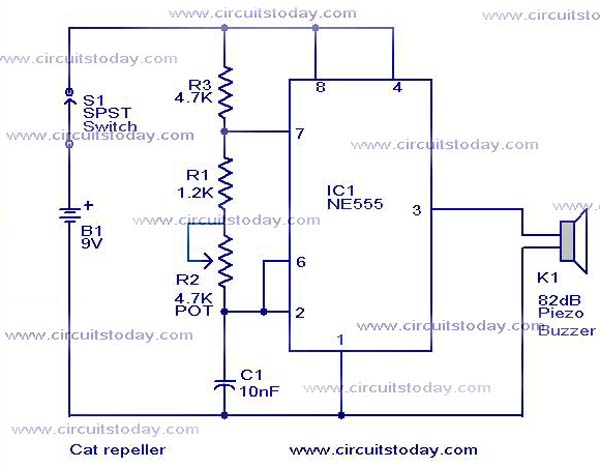
This cat and dog repeller circuit is designed to deter animals from specific areas. The circuit utilizes ultrasonic sound, which is known to provoke a strong response in many animals, particularly cats. The design features an astable multivibrator configuration...
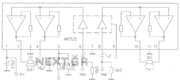
AN7522 is a Panasonic stereo audio amplifier IC that delivers an output power of 3W at 8 ohms. It features a standby function, low static power consumption, and reduced noise levels, requiring fewer external components for stable operation. This...