
variable voltage regulator circuit

The LM317T voltage regulator circuit is designed for versatility in various applications requiring adjustable output voltage. The circuit's functionality is primarily determined by the selection of resistors R1 and R2, which set the output voltage based on the specified formula. The use of a minimum load current is crucial for the stability and proper operation of the regulator, as it ensures that the device remains in regulation.
In practical applications, the choice of R1 and R2 values can be tailored to achieve the desired output voltage. For instance, if a specific output voltage is needed, one can calculate the required resistance values using the output voltage formula. The resistor R1 is typically chosen to be around 120 ohms to maintain the minimum load current, while R2 can be adjusted accordingly to achieve the desired output voltage.
The inclusion of capacitors in the circuit design is essential for enhancing performance. The output capacitor (1 µF tantalum or 25 µF electrolytic) improves the transient response, allowing the regulator to respond quickly to changes in load conditions. The input capacitor (0.1 µF tantalum) serves to filter out high-frequency noise, particularly when the regulator is located away from the power supply filter, ensuring stable operation.
To prevent damage from reverse voltage conditions during power-off scenarios, the addition of a diode across the input and output terminals is a prudent measure. This diode allows current to bypass the regulator, thereby protecting it from potential reverse voltage spikes.
It is also important to consider the transformer specifications when designing this circuit. The transformer must provide an input voltage that is sufficiently higher than the desired output voltage, taking into account the voltage drop across the regulator. A minimum of 3 volts above the output voltage is recommended to ensure reliable operation under full load conditions.
Overall, this LM317T-based variable voltage regulator circuit is a robust solution for applications requiring adjustable voltage, with features that enhance reliability and performance.This is a Variable Voltage Regulator Circuit that is built by LM317T IC. The LM317T is an adjustable 3 terminal positive voltage regulator capable of supplying in excess of 1. 5 amps over an output range of 1. 25 to 37 volts. The device also has built in current limiting and thermal shutdown which makes it essentially blow-out proof.
This circuit ca n be use to make a stable power supply. You can looks the circuit diagram from the figure. The principle work of the circuit is output voltage is set by two resistors R1 and R2 connected as shown below. The voltage across R1 is a constant 1. 25 volts and the adjustment terminal current is less than 100uA. The output voltage can be closely approximated from Vout=1. 25 * (1+(R2/R1) which ignores the adjustment terminal current but will be close if the current through R1 and R2 is many times greater.
A minimum load of about 10mA is required, so the value for R1 can be selected to drop 1. 25 volts at 10mA or 120 ohms. Something less than 120 ohms can be used to insure the minimum current is greater than 10mA. The example below shows a LM317 used as 13. 6 volt regulator. The 988 ohm resistor for R2 can be obtained with a standard 910 and 75 ohm in series. When power is shut off to the regulator the output voltage should fall faster than the input. In case it doesnt, a diode can be connected across the input/output terminals to protect the regulator from possible reverse voltages. A 1uF tantalum or 25uF electrolytic capacitor across the output improves transient response and a small 0.
1uF tantalum capacitor is recommended across the input if the regulator is located an appreciable distance from the power supply filter. The power transformer should be large enough so that the regulator input voltage remains 3 volts above the output at full load, or 16.
6 volts for a 13. 6 volt output. 🔗 External reference
Related Circuits
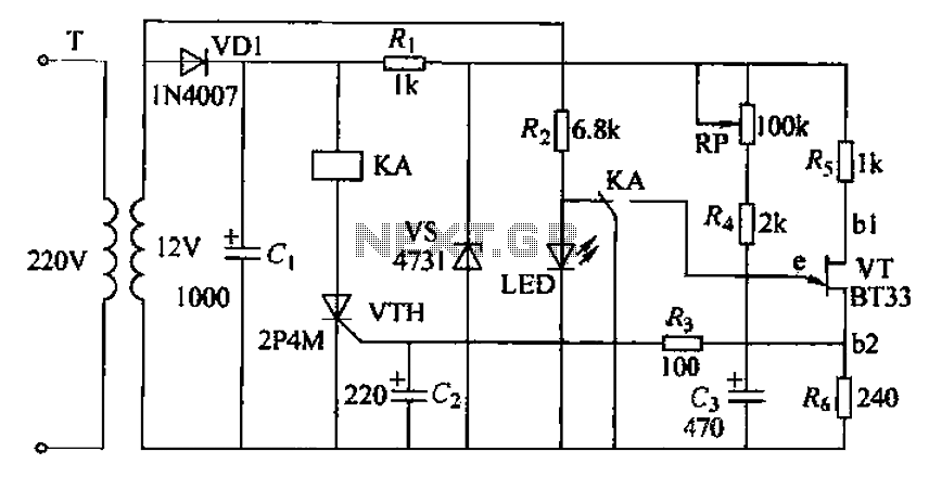
The circuit consists of a delay loop, discriminators, output circuits, power supply, and indicator lights, divided into five parts. The power regulation is achieved through a resistor (R), while the power regulator is constructed using a voltage source. In...
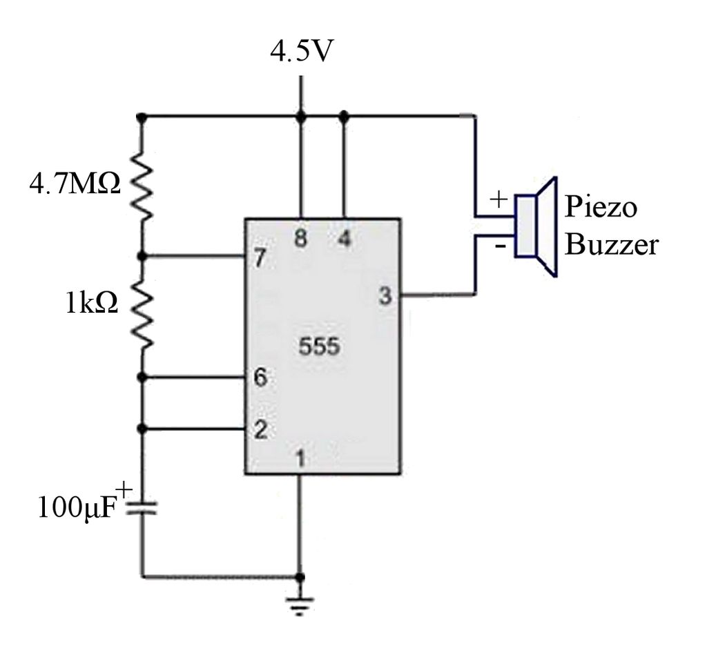
The circuit is a basic 555 timer circuit in astable mode. In this configuration, the integrated circuit (IC) generates a brief pulse to the buzzer at regular intervals. The 555 timer in astable mode operates as an oscillator, producing a...
A gyrator is a circuit that utilizes active devices and transistors to emulate an inductor. In this instance, the gyrator comprises a transistor in conjunction with resistors R1, R3, and capacitor C2. Alternatively, a unity gain operational amplifier could...
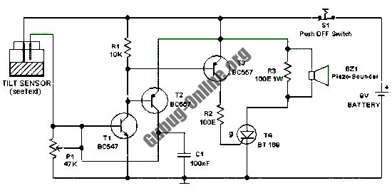
This design features a simple circuit for a tilt sensor alarm that can be constructed using readily available and inexpensive components. The circuit is based entirely on transistor technology. The homemade tilt sensor for this circuit utilizes a standard...
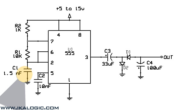
This circuit converts a positive voltage to a negative voltage, resulting in a loss of approximately 1.5 V. For instance, supplying 9 V to the circuit yields an output of -7.5 V. Additionally, this circuit can function as a...
This circuit monitors battery voltage and features a three-LED display. By connecting this circuit to the battery of a vehicle, users can easily determine the approximate voltage at a glance. The battery voltage monitoring circuit utilizes a simple yet effective...
Warning: include(partials/cookie-banner.php): Failed to open stream: Permission denied in /var/www/html/nextgr/view-circuit.php on line 713
Warning: include(): Failed opening 'partials/cookie-banner.php' for inclusion (include_path='.:/usr/share/php') in /var/www/html/nextgr/view-circuit.php on line 713