
BF495 Transistor For Am Transmitter Radio
The BF495 transistor is a high-frequency NPN transistor commonly used in RF applications, including AM transmitters. In this circuit, the BF495 is employed to amplify the audio signal before modulation. The circuit typically consists of several key components: the BF495 transistor, a power supply, an audio input source, and an antenna.
The operation begins with the audio input, which is fed into the base of the BF495 transistor. As the audio signal varies, it modulates the current flowing through the transistor, which is configured in a common-emitter configuration to achieve amplification. The collector of the transistor is connected to a tuned circuit, which consists of an inductor and capacitor that resonate at the desired AM frequency. This tuned circuit is crucial as it allows the circuit to transmit signals effectively over the airwaves.
The output from the collector is then coupled to an antenna, which radiates the modulated signal. The use of ceramic components in the circuit enhances stability and reduces losses, contributing to the overall efficiency of the transmitter. The circuit may also include additional components such as resistors and capacitors for biasing and filtering purposes, ensuring optimal performance.
In summary, the BF495 transistor circuit provides a robust solution for AM transmission, leveraging the characteristics of the transistor and the design of the tuned circuit to achieve effective signal broadcasting.This circuit shows about BF495 Transistor For Am Transmitter Radio Circuit Diagram. Features: powerful AM transmitter, using ceramic .. 🔗 External reference
Related Circuits
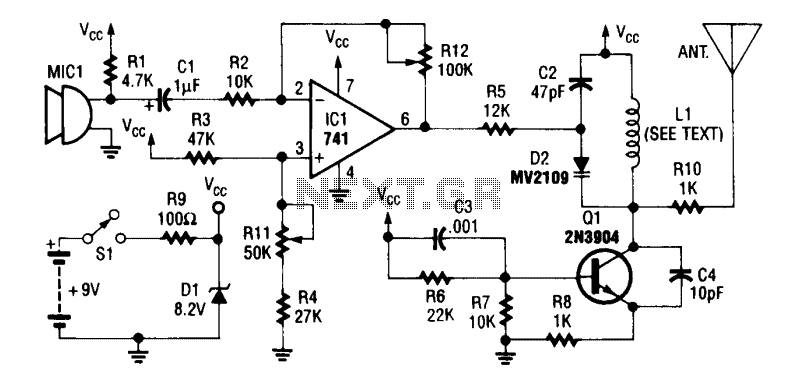
An operational amplifier integrated circuit (741) amplifies the audio signal from microphone MIC1, with resistor R12 adjusting its gain. The amplified audio is directed to the oscillator circuit, which includes transistor Q1 and associated components. D2 is a varactor...
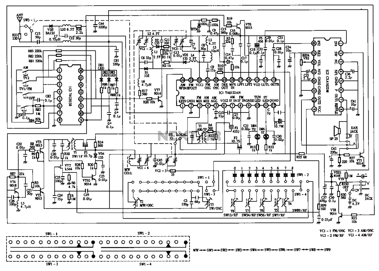
The circuit diagram for the Desheng 119 700 type FM, TV sound, medium wave, and short wave high sensitivity L2-band stereo radio is presented below. The Desheng 119 700 type radio circuit is designed to receive various frequency bands including...
The design shown will test PNP and NPN transistors, diodes and SCRs both "in-situ" (equipment of course de-energised) and also by direct connection to a stand-alone component. It is a simple GO/NOGO test which can identify diode and transistor...
This is a single transistor pump circuit. It is a straightforward circuit that is quite useful and can serve as a foundational component for designing more complex electronic systems. The single transistor pump circuit utilizes a transistor as the primary...
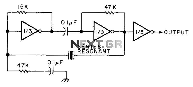
The circuit diagram illustrates the connection of all three components of the series resonant crystal and triple CD4049 inverter. The supply voltage range is between 3 to 15 volts, making it suitable for various applications. This design is compact...
This is a simple electronic thermometer circuit. It is an inexpensive circuit because the probe or sensor used in this circuit is a 2N2222 silicon transistor. The electronic thermometer circuit utilizes the 2N2222 silicon transistor as a temperature sensor. The...