
Bi-Color Indicator Circuit
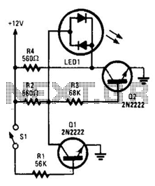
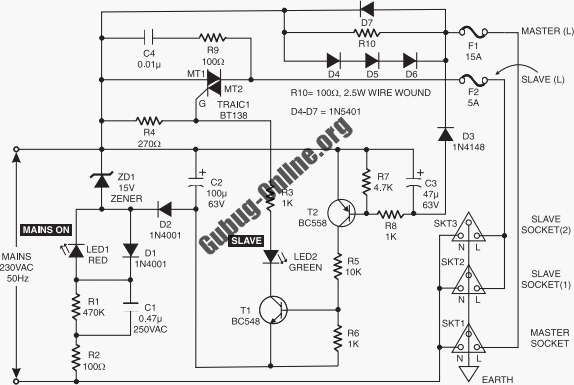
In this circuit, a bi-color LED serves the dual purpose of indicating when the circuit is powered and the status of switch SI, effectively functioning as two indicators.
The described circuit utilizes a bi-color LED to provide visual feedback regarding the operational status of the circuit and the position of switch SI. The LED consists of two elements: a green LED and a red LED, which are integrated into a single package. The circuit's design leverages the properties of bipolar junction transistors (BJTs) to control the LED's behavior based on the state of switch SI.
When the switch SI is in the open position, the voltage divider formed by resistors R2 and R3 ensures that a sufficient base voltage is applied to transistor Q2. This action turns on Q2, allowing current to flow through the green LED element, thus illuminating it. The illumination of the green LED serves as an indicator that the circuit is powered and operational.
Upon closing switch SI, the current flowing through resistor R1 provides base bias to transistor Q1. This results in Q1 turning on, which effectively grounds the voltage divider consisting of R2 and R3. As a consequence, Q2 is turned off, leading to the cessation of current through the green LED. The change in current flow results in the red LED element being activated, indicating that the circuit is under power and that switch SI is engaged in controlling another circuit.
The bi-color LED's functionality is enhanced by the use of BJTs, which allow for reliable switching and clear visual indications of the circuit's status. This design is particularly useful in applications where it is essential to monitor both power status and the state of control switches, providing a compact and effective solution for circuit indication. With SI open, base bias is supplied to Q2 through a voltage divider (formed by R2 and R3), thus turning on the green element in the LED. That indicates that power is being supplied to the project. If you close SI, current through R1 biases Ql on, thereby grounding the voltage divider and turning off Q2.
That reverses the flow of current through the LED, which causes its red element to light. That indicates that the circuit is under power and SI (really a DPDT switch), whose remaining section controls another circuit, is active. In this circuit, a bi-color LED is used to indicate when a circuit is under power and the status of SI. In that way, the LED does the job of two indicators. 🔗 External reference
Related Circuits
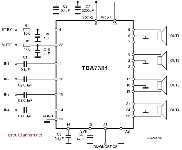
The amplifier is a quad amplifier circuit (amplifier with four inputs and four outputs) based on the TDA7381. This amplifier is designed for car audio systems, but it can also be utilized for other applications. The circuit has a...
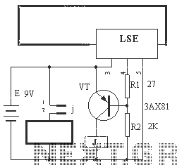
The circuit operation principle of the device illustrated in Figure 13 is as follows: When the barbed wire (Fe) remains intact, the output pin (O) of the LSE is at a high state. Consequently, the transistor (VT) remains off,...
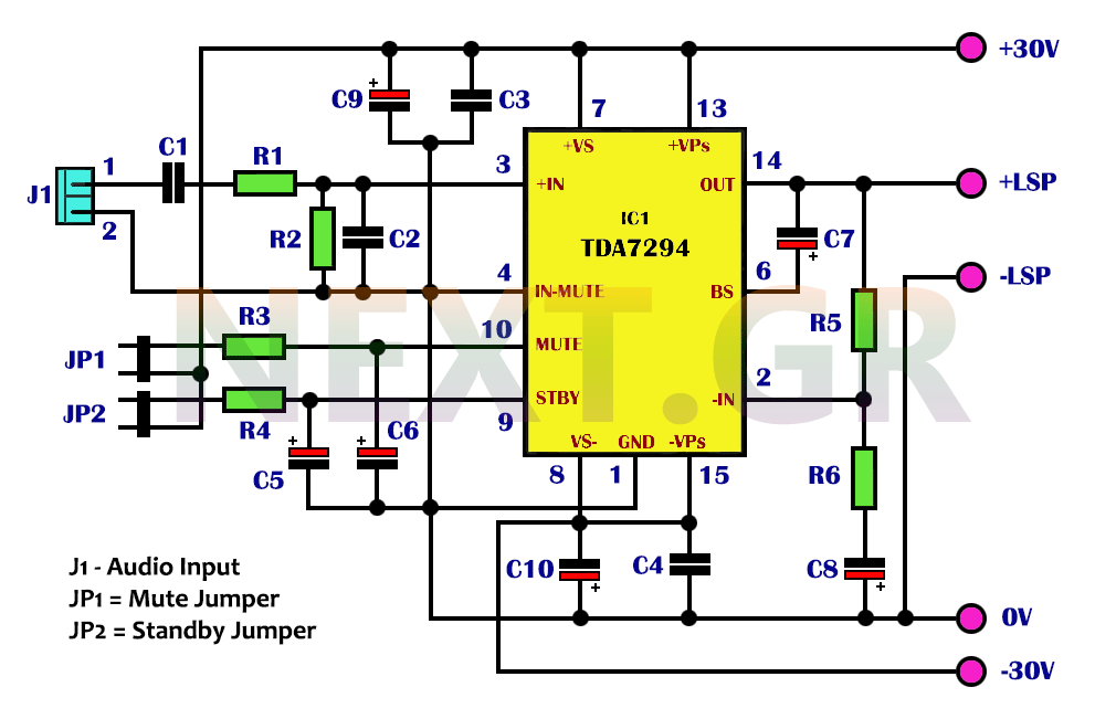
The integrated TDA7294 from SGS Thomson is a high-frequency acoustic power amplifier that boasts true high-precision specifications, making it suitable for various applications. Its standout feature is the significantly higher output power compared to typical amplifiers with similar distortion...
This circuit design features a modular arrangement that enables users to select only the modules best suited to their needs, allowing for the construction of a chain ranging from one to five modules in length. For those seeking a...
Detects clipping in preamp stages, mixers, amplifiers, etc. Single LED display powered by a 9V battery. This circuit is intended for use as a standalone unit. The clipping detection circuit is designed to monitor audio signals in various electronic devices...
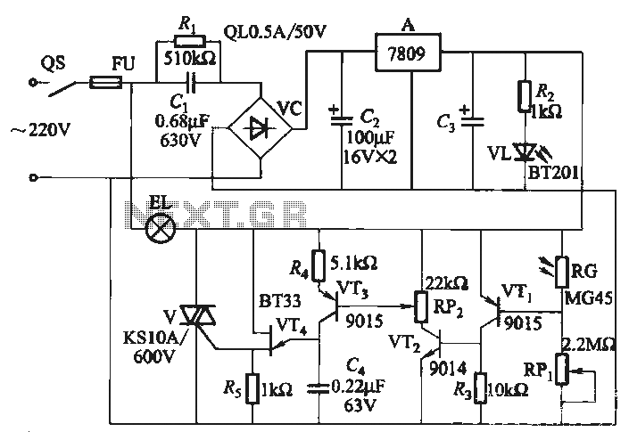
EL auxiliary lights. When the lights dim in the ballroom, EL automatic lights, and ballroom lights dim in a more serious manner. EL light becomes brighter, allowing the inner disco lighting to automatically maintain a certain brightness. A photoresistor...
Warning: include(partials/cookie-banner.php): Failed to open stream: Permission denied in /var/www/html/nextgr/view-circuit.php on line 713
Warning: include(): Failed opening 'partials/cookie-banner.php' for inclusion (include_path='.:/usr/share/php') in /var/www/html/nextgr/view-circuit.php on line 713