
Power disconnection alarm circuit diagram
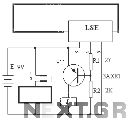
The electronic circuit described operates as a security system that utilizes a barbed wire sensor to detect unauthorized tampering. The core components include a barbed wire sensor (Fe), a logic signal emitter (LSE), a transistor (VT), and a relay (J).
When the barbed wire is intact, it completes a circuit that keeps the output pin of the LSE in a high state. This condition ensures that the transistor (VT) remains in an off state, which prevents current from flowing through the relay (J). As a result, the relay does not engage, and the alarm remains inactive.
In the event that the barbed wire is cut, the circuit is disrupted, leading to a drop in the voltage at the output pin of the LSE from high to low. This transition triggers the transistor (VT) to enter a conductive state, allowing current to flow through it. The activation of the transistor energizes the relay (J), which is designed to close its normally open contact. This closure connects the power supply to the alarm circuit, effectively turning the alarm on.
The design of this circuit emphasizes reliability and responsiveness to tampering events, making it suitable for various security applications. The choice of components, such as the transistor and relay, should be made based on the expected load of the alarm system and the environmental conditions in which the circuit will operate. Proper placement of the barbed wire and the circuit components is crucial for optimal performance and to ensure that the system can effectively detect breaches.Circuit operation principle of the device shown in Figure 13. When the barbed wire Fe intact, LSE's O, feet collusion between its pin output high, the transistor VT end, the relay J is released, the alarm does not work. If Fe barbed wire was cut (any period), then the LSE O, feet equivalent open, it feet is the original high state to a low state, transistor VT conduction, so that the relay J excitation pull its normally open contact j closure, connected to the alarm circuit power, then alarm.
Related Circuits

This simple wind charger circuit project is designed using the LTC1042 monolithic CMOS window comparator, manufactured by Linear Technology. The wind charger circuit utilizes wind power to generate the energy necessary for charging Ni-Cd or lead-acid batteries. When the...

The American Atmel AT89C52 is a low-voltage, high-performance CMOS 8-bit microcontroller chip that contains 8KB of rewritable program memory and 256B of random access data memory (RAM). Atmel's high-density devices utilize non-volatile memory technology and are compatible with the...
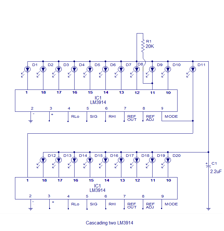
The core of this circuit is the LM3914 from National Semiconductor. The LM3914 is capable of sensing voltage levels and can drive a display of 10 LEDs in either dot mode or bar mode. The selection between bar mode...
Unless a custom-made transformer is available, the circuit design is constrained by the transformer that is accessible. If the primary winding is not center-tapped, the design is limited to an AB driver. A center-tapped primary winding allows for the...
This timer utilizes a basic monostable circuit. The duration for which the relay remains energized, referred to as the ON period, is regulated by the resistor R3 and capacitor C2. Conversely, the duration for which the relay remains de-energized,...

The machine model, commonly used for ESD testing in Japan, is a more severe ESD test. This model simulates metallic contact between the device under test and a charged body. The source capacitor is 200pF with no limiting resistor....
Warning: include(partials/cookie-banner.php): Failed to open stream: Permission denied in /var/www/html/nextgr/view-circuit.php on line 713
Warning: include(): Failed opening 'partials/cookie-banner.php' for inclusion (include_path='.:/usr/share/php') in /var/www/html/nextgr/view-circuit.php on line 713