
Bicycle Speedometer With Hub Dynamo
The circuit described is an innovative solution for overcoming the limitations of traditional wireless speedometers in bicycles. The integration of a Shimano NX-30 hub dynamo ensures a reliable power source, converting mechanical energy into electrical energy efficiently. The use of capacitors C1 and C2, along with diodes D1 and D2, is crucial for voltage doubling, allowing the circuit to maintain adequate power levels even when the dynamo is under load.
The voltage regulator IC2 plays a vital role in stabilizing the circuit's output, ensuring that both the transmitter and the divider IC operate within safe voltage limits. This is particularly important as fluctuations in battery voltage can lead to erratic performance or complete failure of the speedometer. The frequency divider IC1 is essential for translating the dynamo's output into usable pulses for the speedometer, ensuring that each pulse corresponds accurately to a single wheel revolution.
By housing the circuit within the front light, the design not only conserves space but also simplifies wiring and reduces potential signal loss due to distance. The option to adjust the wheel size setting in the cycle computer setup demonstrates flexibility in design, allowing users to tailor the system to their specific needs while minimizing component usage. This thoughtful approach to circuit design enhances the reliability and functionality of the bicycle speedometer, providing cyclists with accurate and consistent speed readings.The idea for this circuit came when the author had problems with the wireless speedometer on his bicycle. Such a device consists of two parts: the cycle computer itself and a transmitter that is mounted on the front fork.
A small magnet is attached to the spokes so that the transmitter sends out a pulse for every revolution of the wheel (as long a s everything has been fitted properly). Since the range of the transmitter is limited (about 75 cm), you`ll be lucky if it works straight away. And when the voltage of the battery starts to drop you can forget it. The following circuit gets round these problems. A Shimano NX-30 hub dynamo has 28 poles. This results in 14 complete periods of a 6 V alternating voltage per revolution (when loaded by a lamp; under no load the voltage is much higher).
C1, C2, D1 and D2 double the voltage of the AC output. Regulator IC2 keeps the voltage to the transmitter and the divider IC at a safe level (12 V, the same as the original battery). The divider chip (IC1) divides the frequency of the signal from the dynamo by 14, so that a single pulse goes to the transmitter for every revolution of the wheel.
This pulse enters the circuit at the point where the reed contact was originally. The circuit is built inside the front light, since it has enough room and a cable from the dynamo is already present. The distance to the cycle computer is smaller as well in that case. The following tip can be used if you want to save yourself a few components. In the author`s prototype the counter divided by 16 and the setting for the size of the wheel was adjusted to 16/14th of the real size in the setup of the cycle computer.
In that case you can leave out D4, D5 and D8. 🔗 External reference
Related Circuits
The microcontroller unit (MCU) will read images from the DataFlash memory via the SPI bus based on the known velocity. It will then send these images to the LED drivers using the SPI bus, controlling the on and off...
The proximity detector detects the movement of PC board pieces as the wheel rotates, generating an output signal with a clear transition between high and low voltage levels, making it suitable for triggering counting or processing circuits. Following this...
This circuit is a mini bicycle bell. The mini bicycle bell is activated by a switch that functions as a button. When the button is pressed, an electric current flows through a 9V electronic circuit via the transistor Q1....
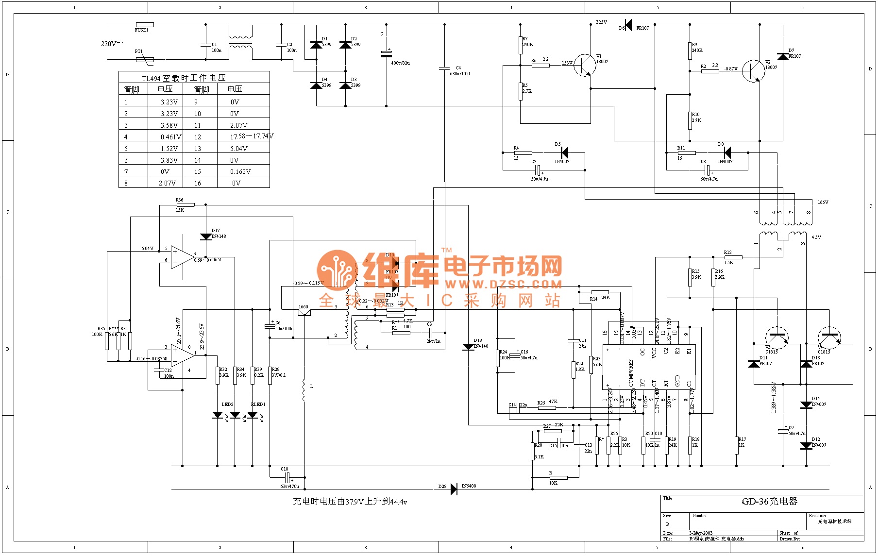
The TL494 is a voltage-driven pulse width modulator produced by the United States company IR. It serves as a switching power circuit in various applications, including displays, computers, and other system circuits. The output transistor of the TL494 can...
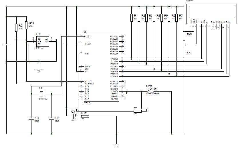
This project involves creating a digital speedometer and odometer using the AT89S52 microcontroller. Testing has been conducted using the Proteus (ISIS) simulator, and the design is functioning correctly. The digital speedometer and odometer project utilizes the AT89S52 microcontroller, which is...
The 555 circuit described is a flashing bicycle light powered by four C, D, or AA cells (6 volts). It features two sets of 20 LEDs that flash alternately at approximately 4.7 cycles per second, utilizing the specified RC...