
simple circuit mini bicycle bel
The mini bicycle bell circuit operates at a nominal voltage of 9V, which is supplied by a standard battery. The circuit employs two transistors, Q1 and Q2, which function as electronic switches. Q1 is responsible for controlling the flow of current when the button is pressed, allowing the circuit to be activated. This activation results in a current being directed to Q2, which in turn powers the speakers.
The use of a capacitor in the circuit serves a crucial role in sound modulation. It acts as a filter that smooths out the electrical signal sent to the speakers, preventing abrupt cessation of sound when the button is released. This capacitor effectively allows for a gradual decay of sound, enhancing the auditory experience.
The schematic diagram provided illustrates the connections between the components, including the power supply, transistors, speakers, and the capacitor. The design is straightforward, making it suitable for hobbyists and those looking to create a simple yet effective bell system for bicycles.
For those interested in further modifications, the circuit allows for the substitution of the mechanical switch S1 with a proximity sensor. This change would enable the bell to activate without direct contact, providing a more modern and user-friendly approach. The PCB design accompanying the circuit simplifies the assembly process, allowing for a more organized and reliable construction of the mini bicycle bell. The downloadable PCB layout ensures that users can replicate the circuit with precision, facilitating ease of use for both novice and experienced electronics enthusiasts.This circuit is a mini bicycle bell. Mini bicycle bell is connected using the bell as a switch. If the button is pressed, an electric current flowing on the 9V voltage electronic circuit through the transistor Q1. because the speakers are connected to the battery using a transistor Q2, when the transistor electrified, the speakers will also be ele
ctrified and sounds. Capacitor is used to the sound of the speakers is not a quick stop. Here is a schematic drawing mini bicycle bell: For the development of this circuit you can replace the switch S1 with the proximity sensor circuit. here I also include a PCB (printed circuit board) of the simple circuit mini bicycle bell and you can also download it.
🔗 External reference
Related Circuits
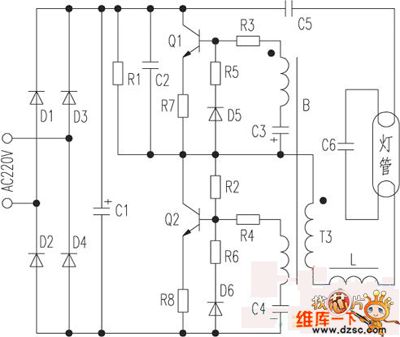
The saving lamp circuit features two main types: glass cover and exposed. The glass cover variants include three series: spherical, cylindrical, and processing types. The first two series consist of four variations: transparent, carved, engraved, and white. These lamps...
Using this low cost project, one can reproduce audio from a TV without disturbing anyone. It does not use any wire between the TV and headphones. Instead of a pair of wires, it uses invisible infrared light to transmit...
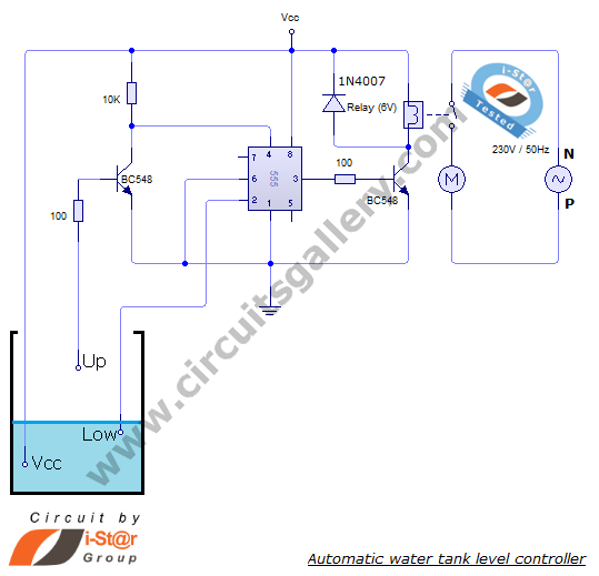
The automatic water level controller circuit is a straightforward engineering project that can automatically switch a domestic water pump on and off based on the water level in a tank. This motor driver circuit can be implemented at home...
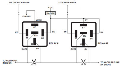
The circuit diagram displayed below illustrates a single-wire vacuum control system for pneumatic locking, commonly utilized in vehicles from Jaguar, Audi, and Mercedes. The circuit operates by managing the vacuum pressure required to engage or disengage the pneumatic locking mechanism....
Class D amplifiers are significantly more efficient than traditional amplifiers; however, this high efficiency is accompanied by increased noise and distortion. The frequency and time-domain characteristics of a Class D amplifier, including its output filter, can be evaluated using...

A Countdown Timer Circuit is a project submitted by a group of students for their ECE 130 - Computer Application class on August 31, 2006, at the University of St. La Salle, Philippines. The seven-segment decoder is utilized in...