
Bicycle LED POV hardware
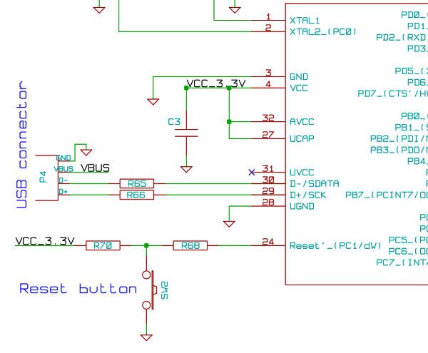
The described circuit operates by integrating several key components to achieve the desired functionality of LED control based on data stored in memory. The microcontroller unit (MCU) serves as the central processing unit, orchestrating the timing and control signals necessary for the system's operation. It communicates with the DataFlash memory using the Serial Peripheral Interface (SPI) bus, a synchronous serial communication protocol that allows for high-speed data transfer.
The MCU is programmed to sample the velocity of the system, which serves as a trigger for reading specific images stored in the DataFlash memory. Upon receiving the velocity data, the MCU initiates a read sequence from the DataFlash, retrieving the relevant image data. This data is then transmitted to the LED drivers, also over the SPI bus. The LED drivers are responsible for controlling the individual LEDs, turning them on and off as dictated by the image data received from the MCU.
Powering the LED drivers is crucial for their operation. In this design, the LED drivers are directly powered by the voltage supplied from two cells, ensuring that they receive sufficient current to drive the LEDs effectively. The choice of two cells suggests a battery-operated system, where the voltage output must be managed carefully to prevent damage to the LEDs.
Additionally, the system incorporates a DC-DC converter circuit, which steps down or regulates the voltage to provide a stable +3.3 volts supply. This voltage is essential for powering the MCU, DataFlash memory, and the Hall effect sensor, which may be used for detecting position or motion within the system. The DC-DC circuit ensures that all components receive the proper operating voltage, enhancing the reliability and performance of the overall system.
In summary, this electronic schematic integrates an MCU, DataFlash memory, LED drivers, and a DC-DC power supply to create a responsive LED control system based on velocity data. Each component plays a vital role in ensuring that the system operates efficiently and effectively.Knowing the velocity, MCU will read the images from the DataFlash memory using SPI bus, and in the correct timing will send them to the LED drivers using SPI bus, turning on and off the LEDs. The voltage of 2 cells will drive directly the LEDs drivers. +3. 3 volts are available for to use by MCU, DataFlash memory and the hall effect sensor, thanks to DC-DC circuit. 🔗 External reference
Related Circuits

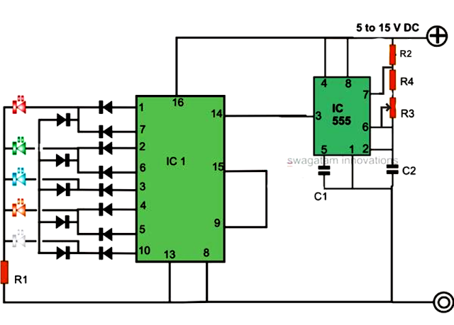
This circuit diagram illustrates the random behavior of a 7-segment LED display. The circuit includes an IC1 (LM555), resistors R1 and R2, and capacitor C2, forming a sensitive multistable configuration. The described circuit utilizes the LM555 timer IC, which operates...
A clock-controlled relay, also known as a time delay relay, allows for the automatic activation of a load, such as a water pump, at a predetermined time. This device utilizes a standard clock mechanism to trigger the circuit, enabling...
Physicians and repair engineers often utilize small light pens for visual examination purposes. While these pens are rugged and can be expensive, their weak point is the bulb, which is a serviceable part. In practice, this often translates to...
The concept for this circuit was developed due to issues experienced with a bicycle's wireless speedometer. This device comprises two components: the cycle computer and a transmitter mounted on the front fork. A small magnet is affixed to the...
An LED light chaser circuit is an electronic configuration designed to illuminate a group of LEDs in a predetermined sequence. A commonly used integrated circuit (IC) for creating this type of LED sequencer circuit is the 4017. This IC...
This relay circuit is controlled by nearly any type of infrared remote controller. The circuit operates under the assumption that most remote controllers utilize high-frequency signals. The relay circuit described functions by receiving signals from an infrared (IR) remote control,...