
Bidirectional motor control

The described circuit employs a DPDT relay to facilitate bi-directional motor control. The relay's configuration allows for reversing the current flow, which is essential for changing the motor's direction. The use of two transistors, specifically a 2N3904 for direction control and a TIP120 for on/off control, ensures that the circuit can handle the required current levels. The choice of transistors is crucial; the 2N3904 is suitable for low current applications, while the TIP120 is designed to manage higher currents typically associated with motor operations.
Incorporating protective components such as a filter capacitor and a flyback diode is critical for maintaining circuit stability and preventing damage from voltage spikes. The filter capacitor helps smooth out voltage fluctuations that can occur when the motor is switched on or off, while the flyback diode protects against back EMF generated by the motor during operation.
For implementations involving very high current motors, substituting the TIP120 with a low on-resistance FET or an SPST relay is recommended. This adaptation enhances efficiency and reliability in the circuit's performance.
The schematic's pin layout aligns with industry-standard relay configurations, making it easier for engineers and hobbyists to replicate the setup using commercially available components. Furthermore, the suggestion to use opto-isolation with 4N33 isolators provides an additional layer of protection against noise and interference, which is particularly beneficial in sensitive applications where microcontroller performance may be affected by motor operation.
Overall, this circuit design effectively demonstrates a straightforward approach to achieving motor control in both directions while addressing potential issues related to voltage spikes and noise interference.One of the simplest ways to get a motor to turn in both directions is by using a double-pole, double-throw (DPDT) relay. Along with the relay, this hookup requires two transistors and two Stamp pins, one for on/off control and the other for direction control.
The diagram below contains the schematic for this setup. The DPDT relay is switching thedirection of current flow through the motor to get it to turn in either direction. The direction control transistor can be a 2N3904 because most relays require much less than 100 mA through the coil to trip the contacts. A TIP120 can also be used for the direction control. A TIP120 is required for on/off control because it must be able to handle the motor currents. For very high current motors, replace the TIP120 on/off control with a low on-resistance FET or with a SPST relay.
In the diagram, the location of the relay pins matches a top view of the DPDT relay sold in the Robot Store (Jameco 174378) and the Radio Shack 275-249A relay. If your program hangs when you switch the motor off or change directions, you might be getting spurious voltage spikes that are causing your program to jump into never-never land.
You`ll know this is happening when the motor keeps spinning when you expect it to stop or change direction. After confirming that this is indeed what is going on and that you don`t have any wiring errors, try adding an 0.
47 micro-farad, 100 V filter capacitor right across the motor terminals. If things are still bad, add a flyback diode between the two common pins on the relay (making sure that the plus or band end of the diode points toward the plus voltage of the battery). Consult the Controlling motors technote for additional info on noise suppression. If things are still not working, you may have to opto-isolate the circuit. With two SPDT relays and two 4N33 isolators, you can construct an isolated, bi-directional control circuit for your motor.
Here`s how. 🔗 External reference
Related Circuits
This integrated circuit is highly efficient and does not require any external glue logic for operation. It features two pins for motor control: one pin is dedicated to controlling the direction of the motor, while the other pin is...
I found some similar circuits but aren't good enough for me. Some circuits measure the water's resistance to determine the level. That is dangerous for drinking water (contamination) or explosive liquids because electricity is in contact with water. The...
This circuit diagram represents a radio-controlled system, commonly used in toy car applications for children. The circuit consists of two main parts: the transmitter and the receiver. The transmitter generates radio signals using an oscillator circuit formed by transistor...
Understanding how to program the PIC microcontroller in theory is beneficial; however, practical learning occurs when the code is executed on a PIC within a circuit. One can either construct a new circuit for each test or utilize a...
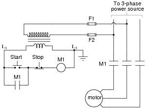
The most challenging aspect of interpreting ladder diagrams, particularly for individuals familiar with electronic schematic diagrams, is the representation of electromechanical relays. The operation of a motor control circuit should be explained, detailing what occurs when the "Run" switch...

The circuit illustrated in Figure 1 generates a precise variable-frequency sine wave intended for use as a general-purpose reference signal. It incorporates an 8th-order elliptic switched-capacitor low-pass filter (IC3), which is clocked by a 100 kHz square wave produced...