
Connect to the PIC Microcontroller

The development board serves as a versatile platform for experimenting with PIC microcontroller programming. It consists of a simple circuit that allows users to easily observe the behavior of their code in real-time. The inclusion of Input/Output (I/O) monitoring via LEDs provides immediate visual feedback, which is essential for debugging and validating the functionality of the code. Users can also integrate switches to simulate different input conditions, enhancing the board's utility during testing phases.
The power supply configuration is critical; the board operates at a nominal voltage of +6V, ensuring compatibility with the PIC's specifications. The flexibility to operate at lower voltages down to +2V allows for a range of experimentation with different power conditions.
The bypass capacitor, C3, plays a crucial role in maintaining signal integrity by filtering out high-frequency noise that could interfere with the PIC's operation. This is particularly important in microcontroller applications where stable voltage levels are necessary for reliable performance.
The 4MHz crystal oscillator (X1) is a fundamental component that provides the clock signal required for the PIC's operation. Utilizing a crystal instead of a resistor-capacitor (RC) network is advantageous due to its superior frequency stability and lower cost, making it a preferred choice in many designs.
Capacitors C1 and C2 are strategically placed to dampen any oscillations that may arise from the crystal oscillator, ensuring that the signal entering the PIC is clean and devoid of interference. This is crucial for maintaining the timing accuracy of the microcontroller, which directly affects the performance of the programmed applications.
Overall, this development board design serves as an effective starting point for users to explore the capabilities of the PIC microcontroller, with the potential for expansion and customization to suit various project requirements.It is all very well knowing how to program the PIC in theory, but the real learning comes when you try your code on a PIC and see the results yourself in a circuit. You could build a circuit each time and program the PIC to see if the program works, or you can make yourself a development board.
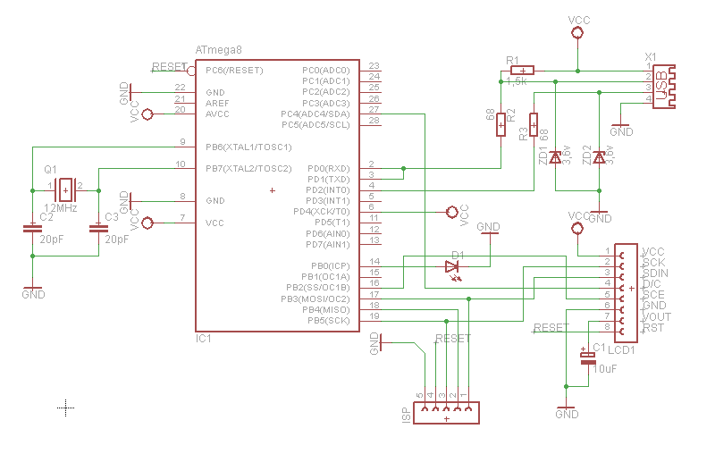
A development board allows you to simulate the environment around the PIC. We have included a circuit diagram to show a very basic and cheap development board. You can, of course add LEDs and switches to this, but We have included the bare bones. You can monitor the Input/Output pins by connecting LEDs directly to the pins, and they will light up when the pins go high. Also, you can add switches to the pins, so that you can select which inputs are high, and which are low.
Basically, what We are saying is if you start with this circuit, you can add whatever you feel necessary. The supply rail is set to +6V, which is the maximum voltage of the PIC. You can use any voltage below this right down to +2V. C3 is known as a `Bypass` Capacitor. All C3 does is reduce any noise on the supply rail. X1 is a 4MHz crystal. You could use a parallel resistor and capacitor circuit, but the cost of the crystal is negligible, and it is more stable.
C1 and C2 help reduce any stray oscillations across the crystal, and get rid of any unwanted noise etc before the signal goes into the PIC. 🔗 External reference
Related Circuits
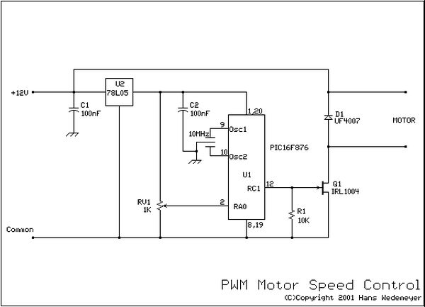
The program utilizes the internal 4 MHz oscillator of the PIC16F628 microcontroller in a two-input alarm circuit. The two-input alarm circuit designed with the PIC16F628 microcontroller leverages the internal 4 MHz oscillator to provide a stable clock signal for operation....
If EAGLE is not available, a full working version can be downloaded from CadSoftUSA. A zip file containing the EAGLE schematics is provided. The EAGLE software is a widely used electronic design automation (EDA) tool that facilitates the creation of...
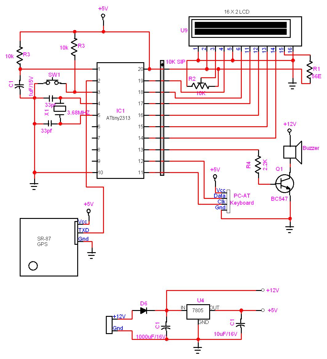
In this project, a GPS module is interfaced with an AVR microcontroller. The ATtiny2313 retrieves location data from the GPS and displays it on an LCD screen. The project involves the integration of a GPS module with the ATtiny2313 microcontroller,...
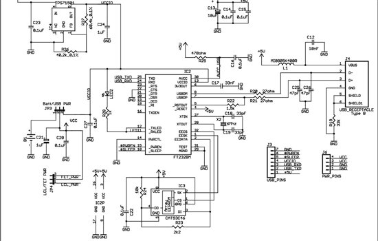
As found in SLAA458, the revised pulse oximeter application, an image of the USB schematic is attached, which is used to output collected data. There are a few questions regarding this schematic: 1) What do J3 and J6 correspond...
What can be done with an old phone, a microcontroller, and plenty of time? One possibility is to connect the old phone's LCD screen to a computer's USB port. Connecting an old phone's LCD screen to a computer using a...
The most significant omission was that the DRUID did not accept confirmation codes (i.e., the solution to the clue) and did not provide directions to the next clue site. Instead, teams had to call in and confirm with Game...