
Bike Battery Charger
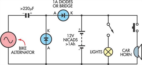
The circuit employs a voltage multiplier configuration, which is essential for stepping up the voltage produced by the bike generator to a level suitable for charging a 12V battery pack. Typically, a bike generator produces an AC voltage that may not be sufficient to charge the battery directly. The voltage multiplier utilizes capacitors and diodes arranged in a specific topology to convert the lower AC voltage into a higher DC voltage.
In this setup, the bike generator's output is first rectified using a diode bridge, which converts the AC output into pulsating DC. Following rectification, the voltage multiplier circuit, composed of multiple stages of capacitors and diodes, is employed to increase the voltage level. Each stage of the multiplier adds to the total output voltage, allowing the circuit to achieve the necessary voltage to charge the 12V battery effectively.
It is crucial to select the appropriate values for the capacitors and diodes to ensure efficient operation and minimize losses. The capacitors should be rated for a voltage higher than the maximum expected output, while the diodes must have a low forward voltage drop to maximize the efficiency of the conversion process. Additionally, the circuit may include filtering capacitors at the output to smooth the DC voltage, providing a more stable charging current to the battery.
Overall, this circuit design is an effective solution for harnessing the energy generated by a bike generator to charge a 12V battery pack, making it suitable for applications where renewable energy sources are utilized.This simple circuit allows a 12V battery pack to be charged via a bike generator. The generator is rated at 3W and with this voltage multiplier circuit pr.. 🔗 External reference
Related Circuits
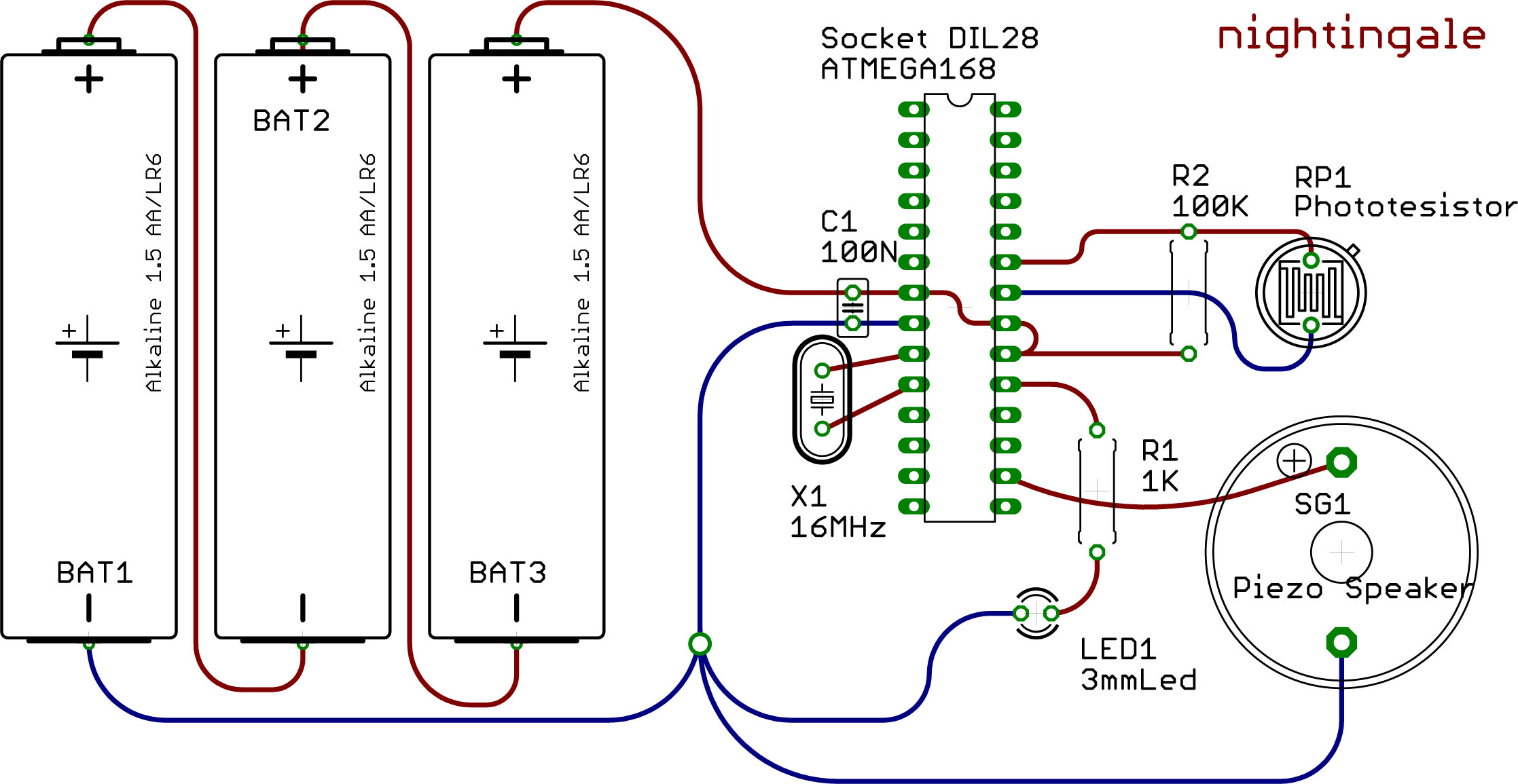
This example demonstrates the utilization of the Watchdog and Sleep functions provided by the ATMEGA 168 microcontroller. These functions are beneficial for developing low-power devices powered by batteries or solar energy. Reduced power consumption is achieved through intermittent operation...
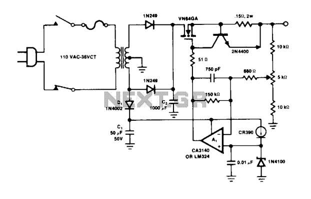
The operational amplifier A1 directly drives the VN64GA with the error signal to control the output voltage. The peak rectifier D1 and capacitor C1 supply the error amplifier A1 and the reference zener. This additional drive voltage must exceed...
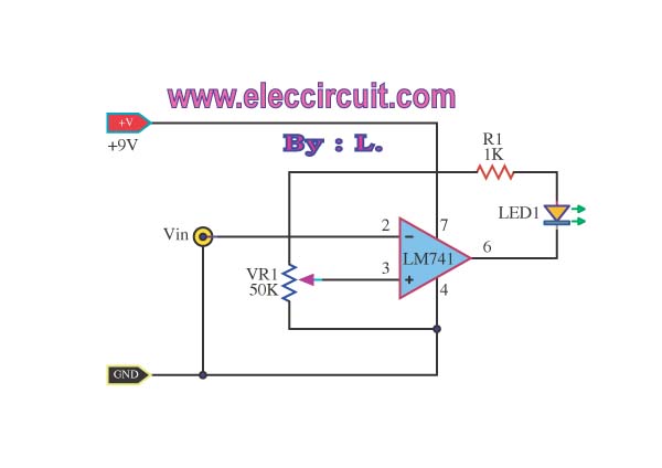
This simple low voltage tester circuit can be used to monitor batteries and other voltage sources for issues, utilizing an LED display and alarm sound. The low voltage tester circuit is designed to provide a reliable method for monitoring the...
This battery charger operates by continuously charging at maximum current, gradually tapering off as the battery approaches full voltage. The full load current from the supply transformer and rectifier section is 4.4A. The current decreases to 4A at 13.5V,...
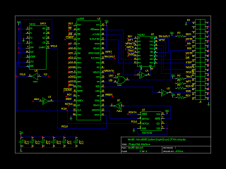
The initial version of the schematics has been completed. There remain several optimizations to be made, particularly concerning the logic gates. The resistors connected directly to the 8085 microprocessor are not strictly necessary, but they may be useful for...
The circuit is designed to be installed in a small enclosure, which can be positioned according to preference. It requires only three connections: one for the positive terminal of the battery, one for the +5 volts supplied by the...
Warning: include(partials/cookie-banner.php): Failed to open stream: Permission denied in /var/www/html/nextgr/view-circuit.php on line 713
Warning: include(): Failed opening 'partials/cookie-banner.php' for inclusion (include_path='.:/usr/share/php') in /var/www/html/nextgr/view-circuit.php on line 713