
Coffee bits and bikes: Mini85
The schematic design process has reached a significant milestone with the completion of the first version. The focus now shifts to enhancing the logic gates, which are critical components that determine the performance and efficiency of the circuit. It is essential to analyze the current logic gate configuration to ensure optimal functionality and to consider potential alternatives that might improve signal integrity and reduce propagation delays.
The inclusion of resistors in the circuit connected to the 8085 microprocessor, while not mandatory, serves as a prudent measure for future scalability. These resistors can provide flexibility for additional components or modifications that may be required in later stages of the project. Their presence allows for easier integration of new features without necessitating a complete redesign of the existing schematic.
Challenges have been encountered in the schematic printing process using gschem. The initial attempts with the light output have highlighted issues with clarity and visibility, prompting a reevaluation of the printing settings. Future attempts will involve adjusting the background color to a lighter shade and eliminating colors entirely to enhance contrast and readability.
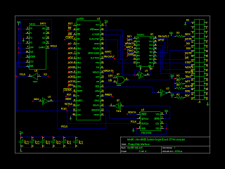
In conjunction with these efforts, generating a comprehensive list of connections is a vital step for the wire-wrapping circuit. This list will serve as a reference to ensure that all connections are accurately made, thereby reducing the risk of errors during assembly. The wire-wrapping technique itself is a reliable method for prototyping and allows for easy modifications, which will be beneficial as the project evolves.The first version of the schematics is finished. There are still some optimizations to do, specially regarding the logic gates. The resistors in the directly connected to the 8085 are not really necessary but handy if a later expansion is needed. It is still difficult to print schematics with gschem, I tried the light output but it is not the best
, I`ll have to try again with light background and no colors. I will also try to print out a list of connections to do the wire wrapping circuit. 🔗 External reference
Related Circuits
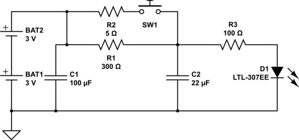
The circuit operates as follows: The LED is typically powered at a low brightness through resistors R1 and R3. SW1 functions as a spring and wire-based accelerometer. When SW1 is activated, capacitor C2 charges rapidly at a rate determined...
It may be necessary to use 10 diodes and various resistors, particularly when utilizing white LEDs. Refer to the Troubleshooting section in step 3 for more details. A sheet of 0.005-inch thick matte drafting film was purchased from a...
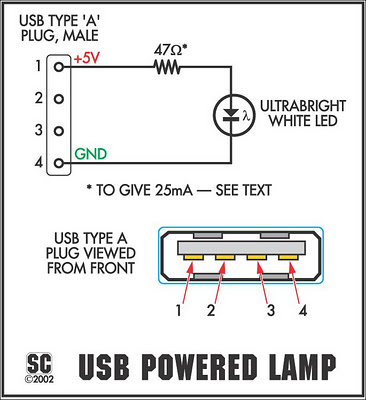
It connects to the USB port and is ideal for checking motherboard switches and jumper settings. Many users may recall a commercial product from a few years ago, the "Itty Bitty Book Light," which was designed to clip onto...
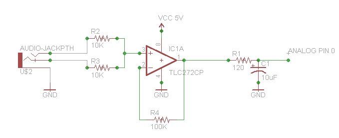
Measuring the temperature of coffee is important because the taste of coffee relies on two main factors: the strength of the coffee and its temperature. Measuring the temperature of coffee can be accomplished using a simple electronic circuit designed to...
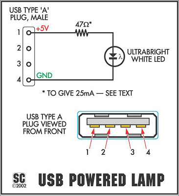
It connects to the USB port and is ideal for checking motherboard switch and jumper settings. Many users may recall a commercial product of a similar nature. This device serves as a USB-based diagnostic tool designed to facilitate the verification...
The circuit presented is designed to prevent burning one's tongue by monitoring the temperature of coffee. It consists of a voltage regulator, a temperature-to-voltage converter, a comparator, and two LEDs. In general, the circuit operates as follows: if the...
Warning: include(partials/cookie-banner.php): Failed to open stream: Permission denied in /var/www/html/nextgr/view-circuit.php on line 713
Warning: include(): Failed opening 'partials/cookie-banner.php' for inclusion (include_path='.:/usr/share/php') in /var/www/html/nextgr/view-circuit.php on line 713