
Bipolar Stepper Motor Driver Circuit
The drive sect ion provides the current-driving capabilities to turn the control signals into coil-driving currents. The drive section also includes protection diodes to prevent back-EMF from the motor coils from destroying the NTE1749/L293 IC.
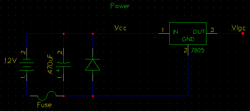
This circuit is designed to power a 12V stepper motor, and use 5V for logic. If your stepper is not 12V capable the circuit will require modification. The circuit can be powered with a standard 12V lead-acid battery. Stepper motor speed is controled by how fast the current direction is switched through the coils (hmm, current direction switched, sound familiar like AC power ). The first step in controlling stepper speed is to generate a clock signal to run the d-flipflops in the control section.
The frequency of this clock signal controls how fast the motor steps. The clock generation circuit shows one way of generating a square-wave signal (clock) at a specific freqeuncy. There are many good sites which describe the operation of the 555 timer IC used in this circuit, such as this one at the university of Guelph.
The frequency of the square wave produced by the 555 is controled by the 0. 18uF capacitor and the 10k pot / 23k resistors. Timing is generated from the charging and discharging of the capacitor through the resistors. The switch between 2. 2k and 23k for R1 selects track (noraml) or slew (fast) modes. The 10k pot allows fine adjustment of the exact tracking speed. The 10nF capacitor attached to the reset pin is very important for noisy envrionments - it prevents false resets. For your setup you may need to modify the resistor or capacitor values to meet your required RPM. The above setup runs at about 200 half-steps per second, or about 30RPM. Calculating the frequency according to R1/R2/C can be done online. Stepper motors require a specific coil energization sequence to turn in one direction. An incorrect sequence will result in the stepper motor vibrating in one place. For examples of an energization seqeuence please refer to the reference sites. Generating the half-stepping sequence is accomplished with four d-flipflops (on two dual d-ff ICs, 74LS74) and four AND gates (on one IC, 74LS08).
The four flipflops form a state machine that moves through the sequence 1000 -> 1100 -> 0100 -> etc. This sequence turns the stepper coils on in such a way that the rotor is aligned fully to one coil, then with two coils on the rotor is halfway to the next step, then fully aligned with the next coil, etc. The Q outputs from the flipflops form the signals that control current direction and state of the motor coils.
The outputs of the 74LS74 could not provide enough current to power my stepper motor. With a very small motor it may be possible to use them directly, in which case a power IC is not necessary. To power my motor, which requires a peak current of about an amp, a dual H-Bidge IC was used, the L293 (or equivalent, like NTE1749).
This IC provides up to two amps peak current. Connection and operation of this IC is fairly simple, the four control lines are connected to the four chip input lines, and the four outputs connect to the two motor coils. The chip enable lines are connected to Vlgc. The two "A" lines go to one coil, and the two "B" lines to the other coil. Use an ohm meter to test the four wires in your motor to figure out the pair for each coil. If two wires are the same coil the resistance will be around 1-15ohm, otherwise it should be near infinite.
Current limiting is an important aspect of stepper drive design. The internal resistance of the motor coils may not be suffecient to prevent over-current. At slow step-rates the impedance in the coils limits the current for only a relativly short time, after which the current will be the voltage divided by the internal resistance of the coil. If this current exceeds the maximum for your motor, your must add some form of current limiting. The 2. 8 Ohm 5 Watt resistors provide resistive current limiting in this circuit. In combination with the 8 Ohm internal resistance of the coils the power resisitors ensure that the current through the coils will never be more than 1.
1 amps. The eight diodes on the output stage (four around each coil) are critical for preventing damage from back-EMF. When outputs to a coil are dropped from 12V to high-impedance the current in the inductor does not stop instantly.
If there is no place for the current to flow when forward voltage is dropped a high voltage spike will occur as electrons "pile up" at the now-"open" switch. The diodes provide a path for the electrons to flow back through the power supply, thereby preventing damaging back-EMF.
Forward/reverse is easy to add to the circuit by switching the polarity of one of the coils. This is accomplished with a DPDT (double-pole double-throw) switch. The circuit can be built in many ways. I would suggest breadboarding the sections first, and maybe even the entire circuit. I chose a prototype board to build the circuit on. This board has copper contacts on the bottom which the various components and wires can be soldered to. Total construction time for the electronics was somewhat longer than I was expecting - soldering took about five or six hours.
Everything worked correctly on the first build. A PCB design would drastically reduce the soldering time. If anyone decides to put one together and is willing to share it, please let me know and I will post it. The finished electronics board is shown to the left. The four sections of the circuit are marked out. Power wiring is on the top of the board, and singals are underneath (not shown). The yellow wires on the top carry the clock singal. I`ve been happy with the performance of this drive. Note that it is loud when running due to stepper motor vibration, but there is no vibration visible at the eyepiece or in photos.
A possible improvement would be to convert to a microstepping design to reduce noise. 🔗 External reference
Related Circuits
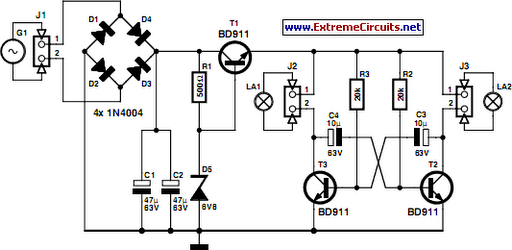
On a mountain bike, a common issue with traditional flashing LED lights from stores is the frequent problem of flat batteries and lights detaching. As an electronics student, a better solution was sought. A front wheel with a built-in...
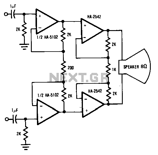
This circuit demonstrates a method to enhance the power capability of a drive system for audio speakers. Two HA-2542 amplifiers are utilized to operate on half cycles only, significantly increasing their power handling capacity. Bridging the speaker, as illustrated,...
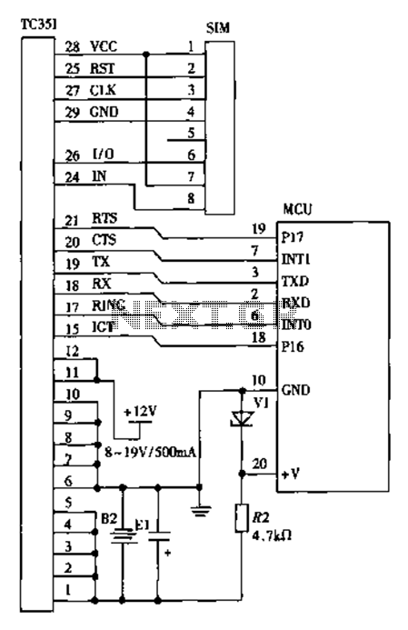
The design of a wireless data communication circuit is primarily intended for motor vehicles and fixed base station systems to facilitate close-range wireless data exchange. The circuit is based on the core chip nRF401 and its associated components. The...
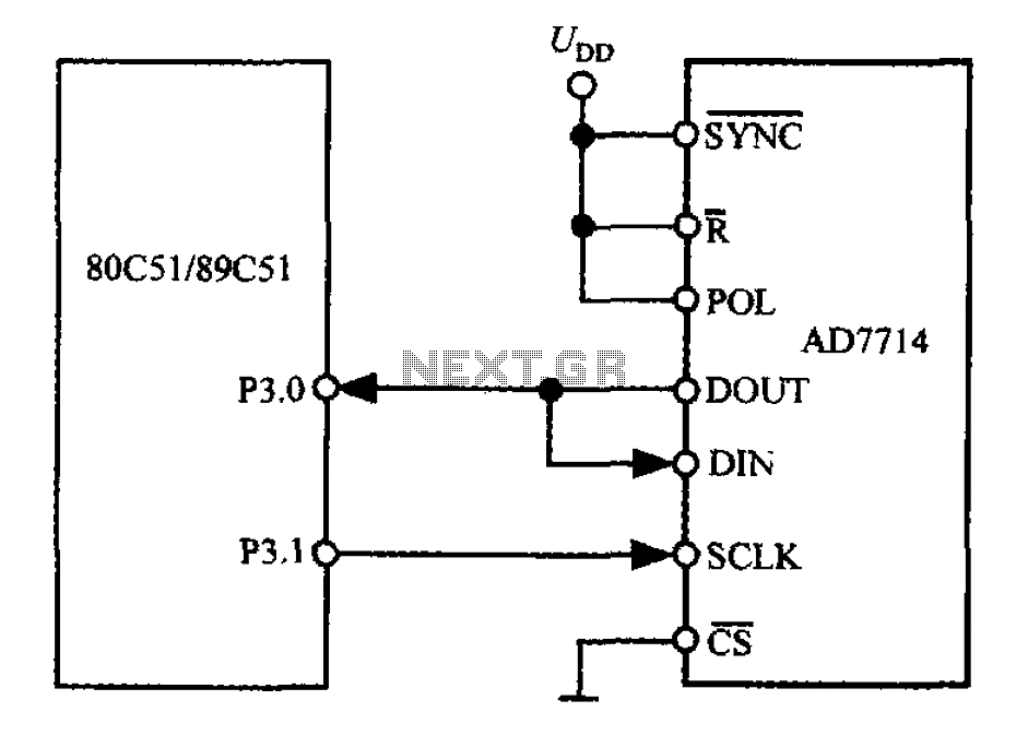
The 3-wire interface to the AD7714 can be utilized with various microcontrollers, including microcontrollers and microprocessors. This 3-wire serial interface is particularly suitable for isolation systems, allowing the use of optical couplers. The interface circuit between the AD7714 and...
This article describes a circuit for a simple single-cell lithium-ion battery charger utilizing the LP2391 regulator IC. The circuit presented is designed for charging a single-cell lithium-ion battery efficiently. The LP2391 is a linear voltage regulator that provides a constant...
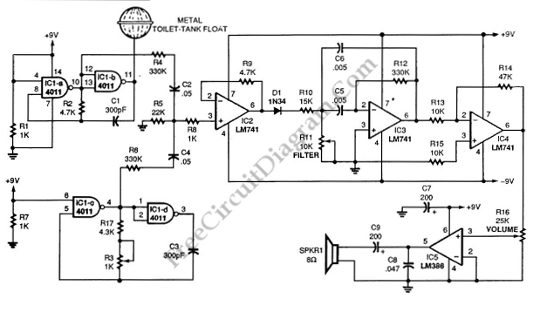
This schematic diagram illustrates a single-chip Theremin circuit. A Theremin is an electronic musical instrument that detects hand movements to control tones and frequency. The circuit employs two separate Colpitts LC oscillators to generate a beat frequency. The frequencies...
Warning: include(partials/cookie-banner.php): Failed to open stream: Permission denied in /var/www/html/nextgr/view-circuit.php on line 713
Warning: include(): Failed opening 'partials/cookie-banner.php' for inclusion (include_path='.:/usr/share/php') in /var/www/html/nextgr/view-circuit.php on line 713