
Digital Remote Thermometer circuit
The circuit operates by utilizing a temperature sensor, such as a thermistor or an RTD (Resistance Temperature Detector), which generates a voltage that varies with temperature. This voltage is fed into a frequency-to-voltage converter circuit, which translates the analog voltage signal into a frequency output. This frequency output is then modulated and transmitted over the mains supply lines, leveraging existing electrical infrastructure for communication.
On the receiving end, a frequency counter is employed to detect the frequency bursts transmitted by the transmitter. The counter processes these bursts and converts them into a digital format suitable for display. The three 7-segment LED displays are configured to show the temperature reading in a clear and user-friendly manner, with the first two displays indicating whole degrees and the last display showing tenths of a degree.
Power supply considerations for both the transmitter and receiver are critical, as they must operate reliably over potentially long distances. The use of appropriate filtering and signal conditioning techniques is essential to minimize noise and interference from other devices connected to the mains supply. Additionally, the circuit can be designed to include features such as calibration adjustments to ensure accuracy and precision in temperature measurements.
Overall, this circuit provides a robust solution for remote temperature monitoring, suitable for various applications where wired connections are impractical or undesirable, while maintaining high accuracy and reliability in temperature measurement.This circuit is intended for precision centigrade temperature measurement, with a transmitter section converting to frequency the sensor`s output voltage, which is proportional to the measured temperature. The output frequency bursts are conveyed into the mains supply cables. The receiver section counts the bursts coming from mains supply and shows the counting on three 7-segment LED displays.
The least significant digit displays tenths of degree and then a 00.0 to 99.9 °C range is obtained. Transmitter-receiver distance can reach hundred meters, provided both units are connected to the mains supply within the control of the same light-meter.. 🔗 External reference
Related Circuits
Due to the low coupling coefficient, the primary self-inductance tends to short out the driving signal. However, utilizing a series/parallel set of capacitors for energy coupling increases the input impedance at resonance, thereby achieving good power transfer efficiency. The...

This circuit represents a remote control unit that utilizes radio frequency signals to operate various electrical appliances. The remote control unit features four channels, which can be expanded to twelve. This circuit stands out from similar designs due to...
Configured with capacitive coupling by inserting a small capacitor between the phototransistor and the bipolar transistor, this relay circuit will respond only to rapid changes. This relay circuit utilizes capacitive coupling to enhance its responsiveness to fast signal changes. The...
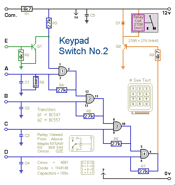
This is a simplified version of the 4-Digit Keypad Controlled Switch. The design has been modified to reduce the complexity of the circuit and the number of components required. Consequently, the code may be somewhat less secure; however, it...
There are digital and analog methods that can be used to compensate for the nonlinearity of a PT100 RTD. Digital linearization can be implemented through various techniques. Compensation for the nonlinearity of a PT100 RTD (Resistance Temperature Detector) is essential...
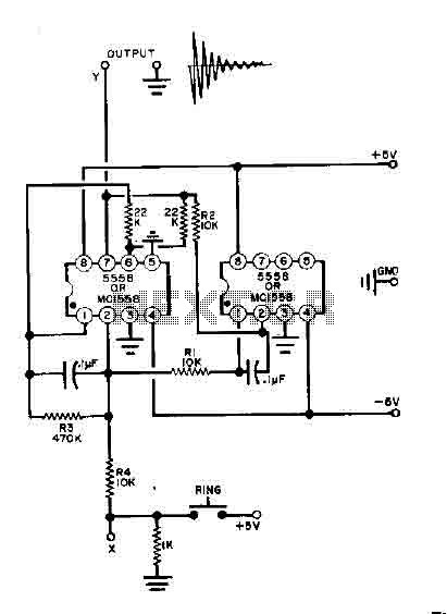
This simple bell circuit utilizes two 555 timers. The frequency is regulated by capacitors that should maintain nearly identical values for optimal performance. Fine-tuning is achieved using resistors R1 and R2. Additionally, the decay time is managed by resistor...