
Single Transistor Half-Wave Peak Detector Circuit
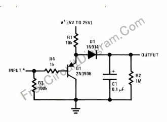
The peak detector circuit utilizes a single transistor, typically configured in a common-emitter arrangement, to achieve its functionality. The primary role of the transistor is to amplify the input signal, allowing for the detection of peak values. The circuit also incorporates passive components such as resistors and capacitors, which are essential for setting the time constant and determining the sensitivity of the detector.
In a standard configuration, the input signal is applied to the base of the transistor, which responds by conducting and allowing current to flow through the collector. A diode is often included in the circuit to ensure that the capacitor, which stores the peak voltage, only charges when the input signal exceeds the previously detected peak. This prevents the capacitor from discharging back through the input.
The output of the circuit is taken from the junction of the capacitor and the diode, providing a voltage that corresponds to the peak value of the input signal. By adjusting the values of the passive components, such as the resistor connected to the base, the sensitivity and response time of the peak detector can be tailored to suit specific application needs.
This type of peak detector circuit is particularly useful in audio processing, signal conditioning, and various measurement applications where it is necessary to capture and hold the maximum voltage level of an incoming signal. Overall, the simplicity of the design, combined with the effectiveness of the peak detection, makes this circuit an attractive option for engineers and hobbyists alike.Using only a single transistor and few passive components, you can build a fairly sensitive peak detector. circuit This peak detector circuit is suitable for. 🔗 External reference
Related Circuits
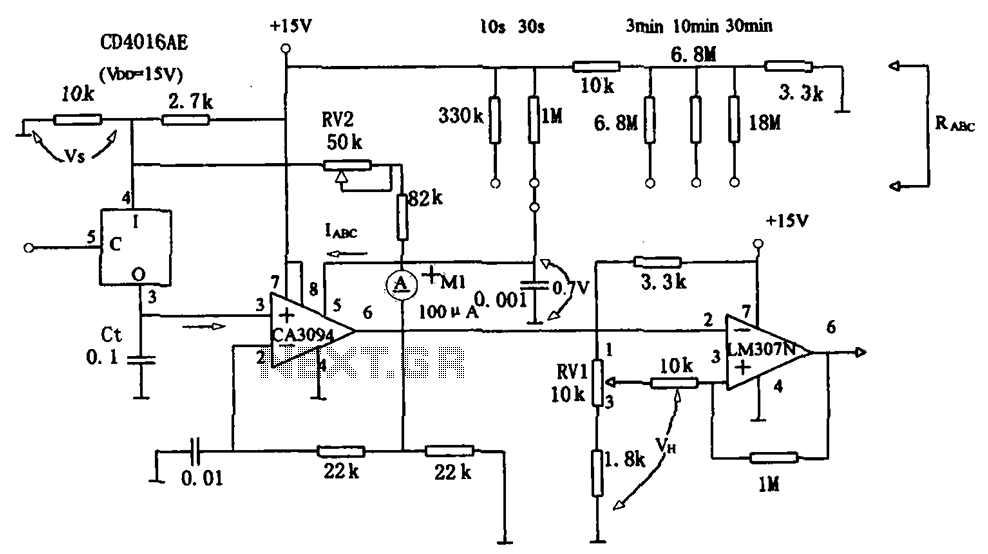
The long timer circuit utilizes an operational amplifier, specifically the CA3094, to control the discharge formula for extended timing. This is typically achieved by adjusting the variable resistor RV1, which alters the timing duration to meet specific requirements. The long...
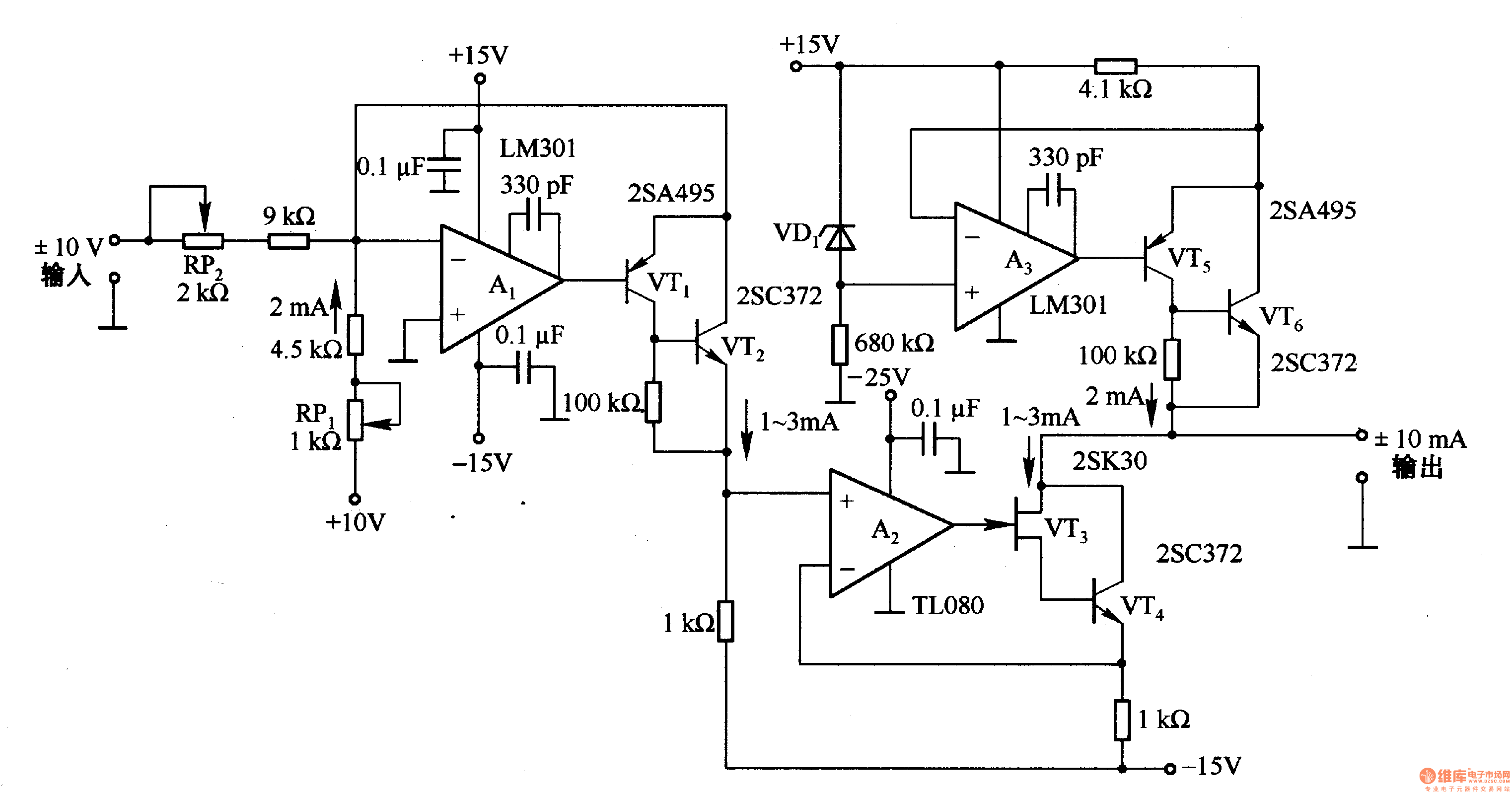
This circuit is designed for voltage-to-current conversion, specifically transforming a ±10V input voltage into a ±1mA output current. The conversion process is facilitated by operational amplifier A1 and transistors VT1 and VT2, which are responsible for altering the current...

This circuit is a graphic equalizer that can be built with a low component count and is controlled using the LA3600 single IC chip. The internal design of the chip utilizes a transistor gyrator circuit, with connections to external...
Even including labor, the actual cost of purchasing, stocking, assembly, assembly errors, more expensive PCBs (with additional holes and larger sizes), and the increased difficulty in tuning would likely result in significantly higher expenses. The analysis of costs associated with...
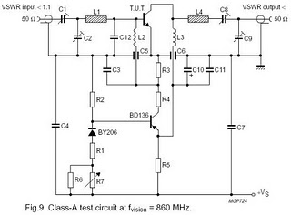
The circuit is designed for driving small UHF TV transmitters, providing a gain of 7 dB and capable of amplifying signals within the frequency range of 470-860 MHz. Key components include resistors, capacitors, and transistors. This circuit serves as a...
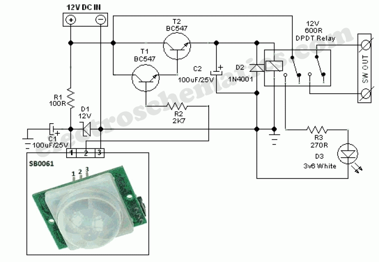
This circuit represents a general-purpose white LED security light equipped with a Passive Infrared (PIR) motion sensing mechanism. The core component of the circuit is the PIR sensor module SB0061, which is a pyroelectric sensor designed for human body...