
Bird Feeder Monitor Circuit
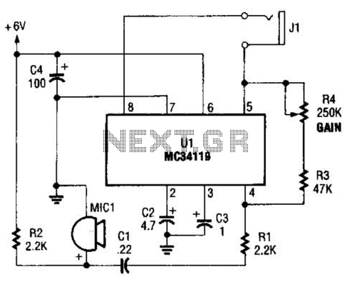
This bird phone circuit utilizes an electret microphone (MIC1) positioned within a funnel to effectively capture sounds from a bird feeder. The funnel design serves to enhance the microphone's sensitivity to distant sounds, focusing the audio capture capability. The MC34119 operational amplifier is central to the circuit, providing the necessary amplification for the microphone's low output signal.
The configuration of the amplifier includes an input resistor (R1) and two feedback resistors (R3 and R4) that establish the circuit's gain. The gain formula, (R2 + R1) / R1 x 2, indicates that the gain is influenced by the ratio of the feedback and input resistors, allowing for precise control over the amplification level. With a maximum voltage gain of approximately 270, the circuit is capable of amplifying the sounds of birds feeding, making it an effective tool for birdwatching enthusiasts.
The output of the amplifier is connected to a 16-ohm speaker, enabling real-time audio playback of the amplified sounds. This setup not only enhances the listening experience but also allows for a deeper appreciation of the subtle sounds of nature. Proper placement of the microphone and amplifier is crucial to maximize sound capture while minimizing background noise, ensuring that the bird phone functions optimally in its intended environment. The first amplifier circuit is a bird phone. In this circuit, the electret mike (MIC1) is mounted in the neck of a large plastic funnel. The amplifier, built around an MC34119 (which is available from D.C. Electronics, P.O. Box 3203, Scottsdale, AZ 85271-3203; Tel. 800-467-7736, and elsewhere), is then placed outside of the funnel with the pickup facing a nearby bird feeder. The output of the amplifier is then connected to a 16- speaker. The amplifier`s voltage gain is determined by the values of the input resistor (Rl) and the feed-back resistor (R3 and R4, respectively).
The differential gain of the amplifier is given by: R2 + RJR} x 2. With the component values shown, the maximum voltage gain is about 270. This permits listening to the activity at the bird feeder. 🔗 External reference
Related Circuits
The DW L11 capacitor steps down voltage into the Jenru half crossing according to Yin electrical specifications. After receiving power at the bin CI SH output terminal, it regulates the voltage to liVI/r j, ensuring a right cut in...
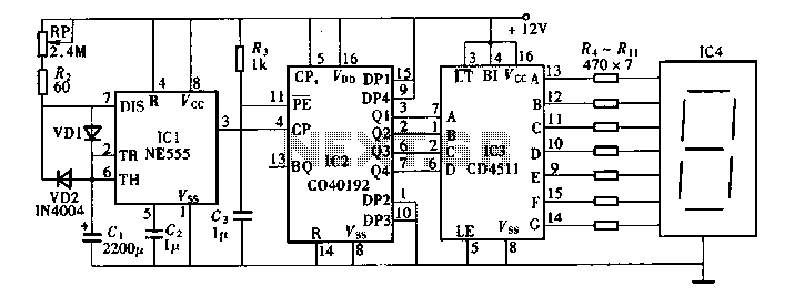
Digital timers feature a clear and precise display. They represent time intervals based on pulse signals, which are decoded by a digital device with a digital display unit. The circuit described pertains to a digital display for these timers,...
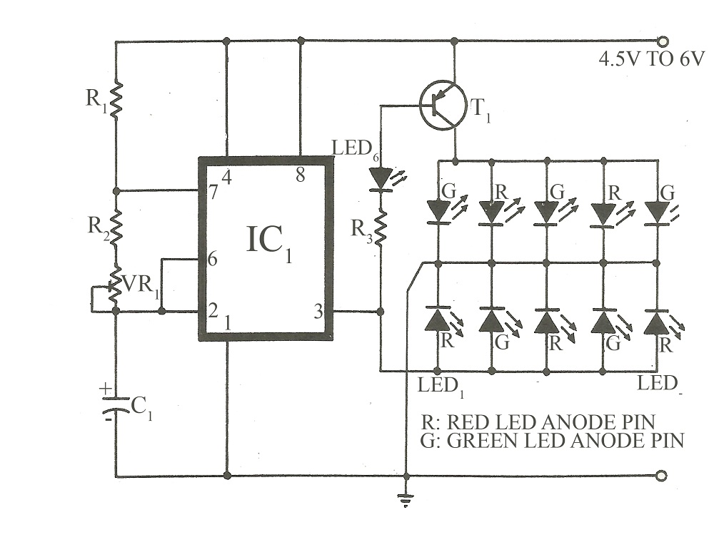
This circuit is similar to various published flasher circuits that utilize the IC 555 as a free-running multivibrator. The primary distinction is in the method of flashing bi-color LEDs. When the output at pin 3 of the IC 555...
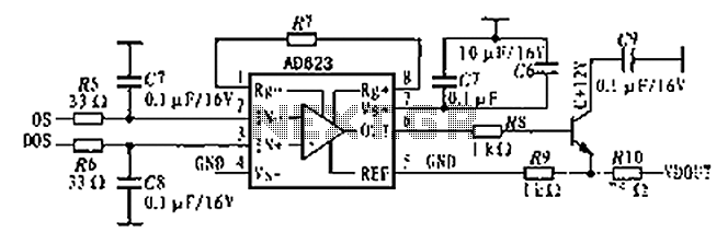
The AD623 is an integrated 3-way amplifier that can operate with either a single or dual supply. It features high common-mode rejection ratio (CMRR) and low voltage drift, along with programmable gain control via an external resistor. All components...
This circuit is designed for alerting purposes after a specified duration has elapsed. It is suitable for table games that require a fixed time limit to answer a question or to move a piece, serving as a modern substitute...
.png)
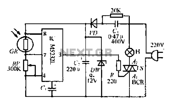
Have you ever considered implementing your own home security alarm system? It is one of the simplest and most interesting circuits for electronics beginners. The new home security equipment utilizes a Light Dependent Resistor (LDR) to detect security breaches....
Warning: include(partials/cookie-banner.php): Failed to open stream: Permission denied in /var/www/html/nextgr/view-circuit.php on line 713
Warning: include(): Failed opening 'partials/cookie-banner.php' for inclusion (include_path='.:/usr/share/php') in /var/www/html/nextgr/view-circuit.php on line 713