
birdie doorbell circuit

This doorbell circuit utilizes a basic configuration to generate sound through a loudspeaker, with the primary control mechanism being an NPN transistor. The design is straightforward, allowing for flexibility in component selection and adjustments based on user preferences. The starting point for the resistor P1 at 220 Ohms provides a baseline for tuning the circuit for optimal sound output.
The bell transformer (L1) plays a crucial role in the circuit, as it converts the low voltage from the power source to a higher voltage suitable for sound generation. In cases where a bell transformer is not available, a 9-volt battery or wall adapter can be employed, ensuring that the circuit remains functional. The inclusion of diode D1 is vital for safeguarding the circuit against incorrect polarity connections, which could potentially damage the components.
The use of a general-purpose PNP transistor (T1) allows for versatility in component selection, as various PNP transistors can be utilized without significant impact on circuit performance. The second transformer (L2) sourced from an AM radio contributes to the sound modulation, and experimentation with different transformers is encouraged to achieve the desired audio effect.
The loudspeaker selection is also important; an 8 Ohm speaker rated for at least 200 milliwatts ensures adequate sound output without distortion. A 2-watt speaker is a suitable choice, providing ample power handling for the circuit's requirements. Overall, this doorbell circuit design allows for customization and experimentation, making it an engaging project for electronics enthusiasts.This is a design circuit for a doorbell. This circuit can produces a sound like bird sound. This circuit controlled by transistor NPN. This is the figure of the circuit. The operation of the circuit is beginning when P1 is of experimental value. Start with 220 Ohms or so and modify to suit your needs. The transistor is a general purpose kind and i s not critical, almost any PNP type will work. L1 is a bell-transformer which is usually already present in the house. If you wish, you could use a battery instead of the bell transformer. Just hookup a 9-volt battery (or wall adapter)to points `A` and `B` (A=+) the diode (D1) is to protect the circuit from accidental polarity reversal and is optional, but required as a rectifier for use with the bell transformer. The transistor T1 is a General Purpose PNP transistor and probably anything will work. L2 comes out of an old am transistor radio. They look like miniature transformers and are usually colored red or green. You have to fiddle with different transformers as the sound can vary depending on the value. The loudspeaker is a 8 Ohm type and must be larger than 200milli-Watt. I used a 2Watt type, but anything over 0. 2W will do. 🔗 External reference
Related Circuits
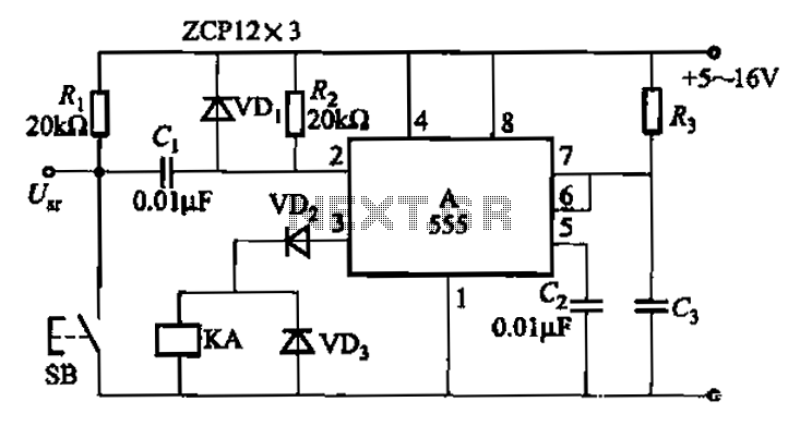
The 555 integrated circuit is utilized in a delay circuit configuration, functioning as a one-shot timer. The delay time can be adjusted using resistor R3 and capacitor C3. Typical values for R3 range from 1 kΩ to 10 MΩ,...
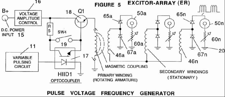
A power supply system utilizes a generator as a source of fuel to separate hydrogen and oxygen gases from natural water. It has the capability to control gas production by varying the amplitude of the voltage and/or the pulse...
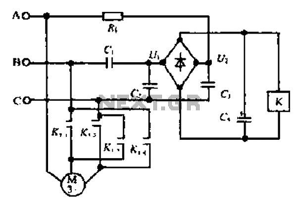
Composition ratio circuit. The circuit consists of resistors and capacitors that form a shift register circuit with diodes VD1 to VD4, creating a bridge for electric current. Capacitor C4 is utilized for filtering applications and for eliminating instantaneous relay...
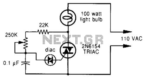
A phase-controlled dimmer delays the triac turn-on to a selected point in each successive AC half cycle. This circuit is suitable only for incandescent lamps, heaters, soldering irons, or universal motors that have brushes. A phase-controlled dimmer is an electronic...
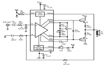
The LME49810 audio amplifier schematic is depicted in the accompanying circuit diagram. Based on the LME49810 datasheet, this component is a high-fidelity audio power amplifier driver intended for use in applications such as audio-video receivers, guitar amplifiers, powered studio...
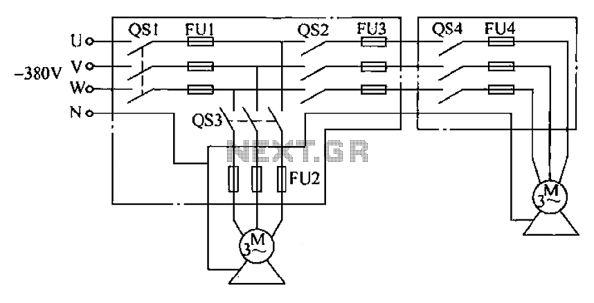
The agriculture and electrical power harrow plow power cord must consist of four rubber cables, with one core wire designated as the ground wire. The traction machine housing must be properly grounded. The two traction power machines are connected...