
Phase-Controlled Dimmer Circuit
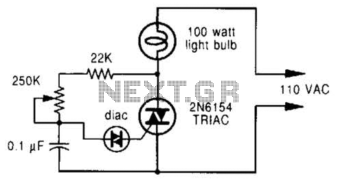
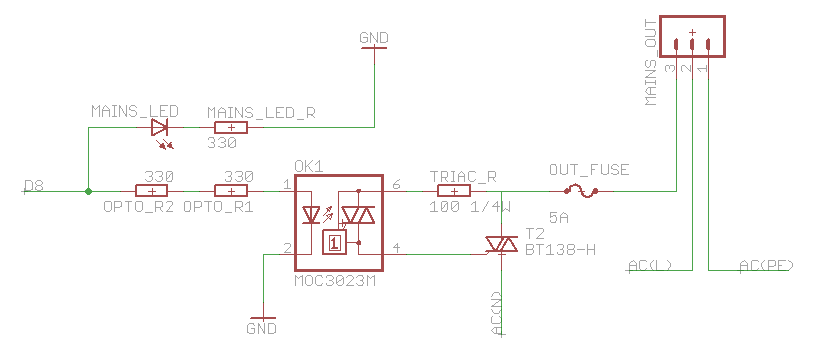
A phase-controlled dimmer is an electronic device that modulates the power delivered to a load by delaying the conduction angle of the AC waveform. The core component in this circuit is a triac, which acts as a switch that can control the flow of current through the load. The operation of the dimmer is based on the principle of phase control, where the triac is triggered at a specific point during each half cycle of the AC waveform.
The circuit typically includes a control circuit that generates a trigger pulse for the triac. This control circuit may utilize a microcontroller or a simple RC timing circuit to determine the delay before the triac is turned on. By adjusting the delay, users can control the brightness of the lamp or the heat output of a heater. For example, a longer delay results in a dimmer light or less heat, while a shorter delay allows more current to flow, increasing brightness or heat output.
It is important to note that this type of dimmer is specifically designed for resistive loads, such as incandescent lamps and heating elements. The dimmer is not suitable for inductive loads, such as transformers or inductive motors, as these can cause the triac to malfunction or operate inefficiently. Universal motors, which have brushes and can operate on AC or DC, are compatible with this type of dimmer due to their resistive characteristics during operation.
In summary, a phase-controlled dimmer provides a simple and effective means of controlling the power to specific types of electrical loads by manipulating the timing of AC waveform conduction through a triac. Proper application and understanding of the circuit's limitations are essential for safe and effective use. A phase-controlled dimmer delays the triac turn-on to a selected point in each successive ac half cycle. Use this circuit only for incandescent lamps, heaters, soldering irons, or universal motors that have brushes. 🔗 External reference
Related Circuits
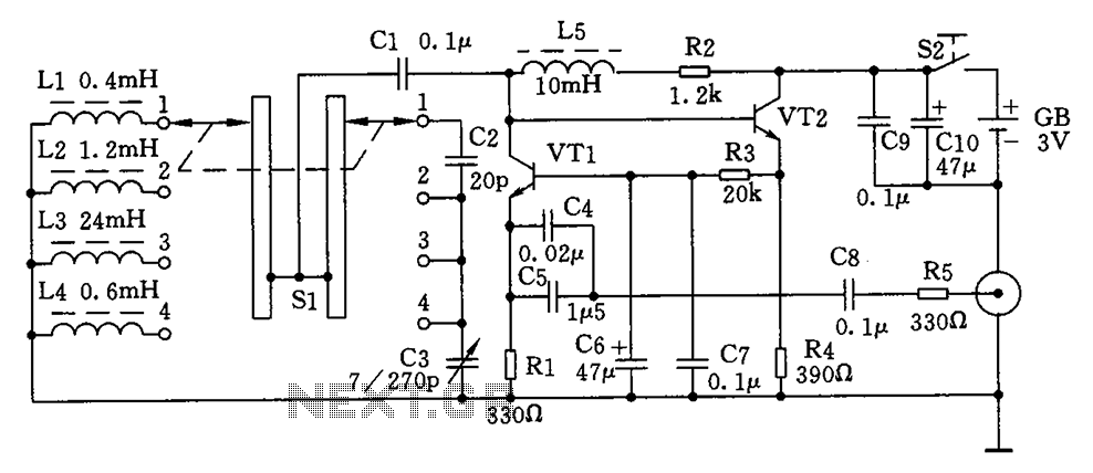
This is a simple high-frequency signal generator. By changing the inductance of the LC resonant circuit using the band switch S1, the high-frequency oscillation frequency range can be altered. The generator is divided into four frequency stages: the first...
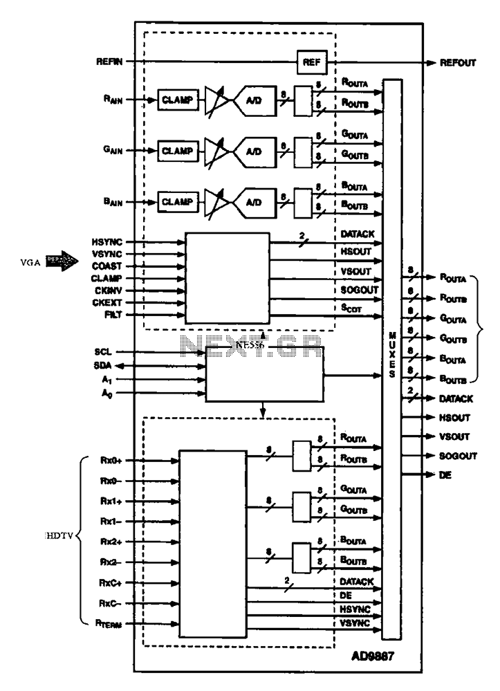
The AD9887, a commonly used video A/D converter for liquid crystal televisions, is capable of converting analog red, green, and blue (R, G, B) signals into digital signal outputs. The AD9887 is a high-performance analog-to-digital converter (ADC) specifically designed for...
This circuit is designed to connect stereo outputs from four different sources or channels as inputs, allowing only one of them to be selected and connected to the output at any given time. When the power supply is turned...
The 555 timer is utilized as a clock source to drive the RS7490 decimal counter, providing a BCD output to a 7-segment LED display. The clock frequency can be adjusted by changing the value of resistor R1. The circuit operates...
The heatsink on the triac is somewhat unclear. A maximum value of 10°C/W has been calculated, which raises concerns. The calculation is as follows: (maximum temperature - room temperature) / (maximum on-stage voltage * (milliamps / voltage) - junction-to-base...
A new user has recently discovered a Laser Alarm System and has decided to explore this project. The Laser Alarm System is a security device that utilizes laser beams to detect unauthorized entry or movement within a designated area. The...
Warning: include(partials/cookie-banner.php): Failed to open stream: Permission denied in /var/www/html/nextgr/view-circuit.php on line 713
Warning: include(): Failed opening 'partials/cookie-banner.php' for inclusion (include_path='.:/usr/share/php') in /var/www/html/nextgr/view-circuit.php on line 713