
Blanking Circuit for Oscilloscope
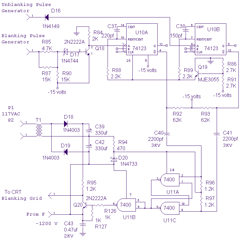
The described circuit functions as a blanking mechanism for a cathode-ray tube (CRT) display, specifically designed to activate just prior to the retrace period of the CRT's operation. This timing is critical as it prevents the display from showing unwanted artifacts during the retrace interval, thus ensuring a clear visual output.
The circuit operates at a high negative voltage of -1200 volts, which is the potential level at which the CRT operates. To accommodate this high voltage, the blanking circuit is designed to function within the same voltage domain. The isolation of the blanking circuit from the rest of the oscilloscope's electronics is achieved through the use of capacitors C40, C41, and C43. These capacitors serve a dual purpose: they provide the necessary coupling to allow the blanking signal to control the intensity grid while protecting the sensitive components of the oscilloscope from high voltage transients that may occur during operation.
In the schematic, the gates controlling the intensity grid are connected to the output of the blanking circuit, ensuring that the intensity of the CRT beam is modulated appropriately during the retrace period. The capacitors' values and types should be selected based on their voltage ratings and frequency response characteristics to ensure reliable performance at the operating voltage of -1200 volts.
Overall, the design of this blanking circuit is essential for maintaining the integrity of the displayed waveform on the CRT, allowing for accurate and clear visual representation of the electronic signals being measured. Proper implementation will enhance the functionality of the oscilloscope while ensuring user safety and equipment longevity.This circuit blanks the CRT starting just before retrace begins. Since the CRT sits at a -1200 volt potential, the blanking circuit must also be based at -1200 volts. Note the capacitors, C40, C41, and C43 which allow the gates that drive the intensity grid of the CRT to be isolated from the other electronics within the oscilloscope.
🔗 External reference
Related Circuits

The sensor must be positioned at an angle of approximately 30 to 45 degrees relative to the ground. This orientation facilitates the drainage of rainwater, preventing accumulation that could trigger the alarm due to water retention on the sensor....

This design circuit serves as a converter utilizing the LM2623A ratio adaptive circuit to drive a digital camera motor. It generates 5 volts from input voltages that range between 1.8 and 4.5 volts. The circuit's duty cycle, while not...
The purpose of this circuit is for research and education. Assistance is sought in acquiring components for simple RF circuits, as well as tutorials or schematics. The requester is facing challenges in locating quality resources for beginner-level RF circuit...

Driving a D/A converter using an A/D converter provides an overall analog-hold function. Although this function has limitations in output resolution, it offers zero voltage droop and infinite hold time. The A/D converter depicted (IC1) features a 12-bit compatible...
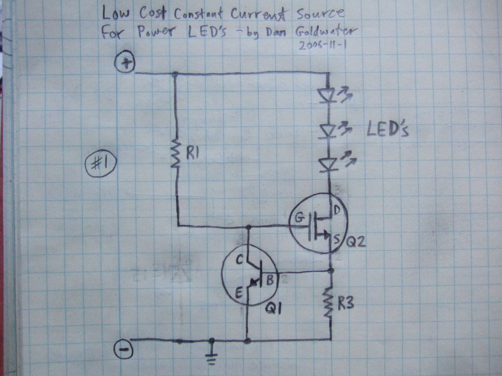
Here is a simple and inexpensive ($1) LED driver circuit. The circuit functions as a constant current source, ensuring that the LED maintains consistent brightness. The LED driver circuit is designed to provide a stable current to the LED, which...
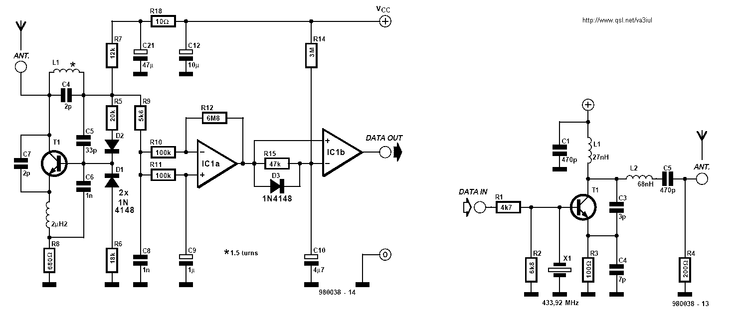
Fixed-value capacitors are disc ceramics. C1, C4, C5, C6, and C8 are NPO ceramic or polystyrene. C2 is a 25-pF ceramic trimmer and C3 is a 15-pF miniature air variable capacitor. The resistors are ¼ watt carbon film or...
Warning: include(partials/cookie-banner.php): Failed to open stream: Permission denied in /var/www/html/nextgr/view-circuit.php on line 713
Warning: include(): Failed opening 'partials/cookie-banner.php' for inclusion (include_path='.:/usr/share/php') in /var/www/html/nextgr/view-circuit.php on line 713