
simplest light with constant-current LED circuit
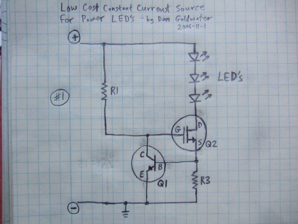
The LED driver circuit is designed to provide a stable current to the LED, which is essential for maintaining its brightness and preventing damage due to overcurrent. The circuit typically includes a voltage source, a current-sensing resistor, and a transistor or integrated circuit that regulates the current flow.
In a basic configuration, the voltage source is connected in series with the LED and the current-sensing resistor. The resistor is placed in such a way that it allows a small portion of the current to flow through it, creating a voltage drop that can be monitored. The transistor, which acts as a switch, is connected to the resistor. When the current through the LED increases, the voltage across the resistor also increases. This change is detected by the transistor, which then adjusts its conduction state to limit the current flowing through the LED.
The choice of components is critical in determining the performance of the LED driver circuit. The current-sensing resistor should be chosen based on the desired current level for the LED, and the transistor must be capable of handling the required current without overheating. Additionally, the circuit may incorporate a heat sink to dissipate heat generated by the transistor during operation.
For applications requiring higher efficiency, a switching regulator can be utilized instead of a linear regulator. This approach minimizes power loss and maximizes the efficiency of the LED driver circuit, making it suitable for battery-operated devices.
Overall, this simple LED driver circuit exemplifies a cost-effective solution for powering LEDs while ensuring reliable operation and longevity.Here`s a really simple and inexpensive ($1) LED driver circuit. The circuit is a constant current source, which means that it keeps the LED brightne.. 🔗 External reference
Related Circuits
As shown in the figure, D187 is a UART with its RX/TX signals connected through optocouplers N21, N22, and N29, providing complete optoelectronic isolation for the RS-485 communication interface receiver/transmitter D28 and microprocessor D211. D197 serves as a generator,...
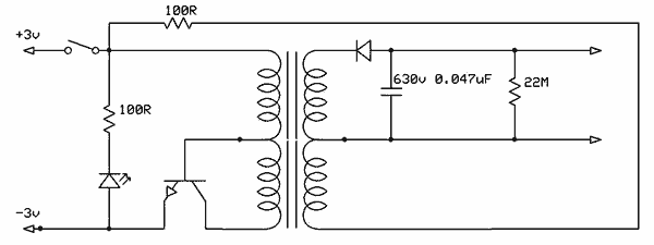
Free energy motors and generators are available for purchase, featuring plans for overunity devices. These devices resemble oscillators used in Joule thief circuits, although there may be some errors present in the designs. However, the concept remains clear. Free energy...
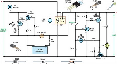
This circuit is designed to switch power to a Peltier cooler in a vehicle. Power is supplied to the load from the vehicle's battery when the ignition switch is on and from an SLA auxiliary battery when the ignition...
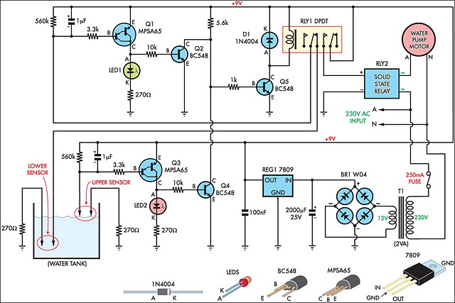
This circuit is designed to fill a header tank for a reticulated water supply on a farm. It serves eight troughs located in different paddocks, where a lack of water could have serious consequences for livestock. Previously, the tank...
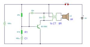
The simple bell circuit without IC. It includes a doorbell circuit that can produce different sounds using integrated circuits, transistors, and resistors. The circuit utilizes a coded trigger mechanism to differentiate between various visitors. When the button is pressed,...
This circuit is a constant current protection type that limits the output current to a specific value in cases of over-current and short-circuit conditions. When the output current exceeds this limit, the output voltage decreases. The CW200 power management...
Warning: include(partials/cookie-banner.php): Failed to open stream: Permission denied in /var/www/html/nextgr/view-circuit.php on line 713
Warning: include(): Failed opening 'partials/cookie-banner.php' for inclusion (include_path='.:/usr/share/php') in /var/www/html/nextgr/view-circuit.php on line 713