
Bldc Motor Control Kit With Ata6833/ Ata6834

The T7024 is engineered to facilitate efficient signal processing in wireless communication systems operating at 2.4 GHz to 2.5 GHz. Its integrated design minimizes the need for external components, thus reducing overall system complexity and enhancing reliability. The Power Amplifier (PA) is optimized to provide high output power while maintaining linearity, which is crucial for minimizing distortion in transmitted signals.
The Low-Noise Amplifier (LNA) is designed to amplify weak incoming signals, ensuring that the system can effectively receive data even in environments with significant noise. The LNA operates with a low noise figure, which is essential for maximizing the signal-to-noise ratio (SNR) in the received signal.
The switch driver for the PIN diode antenna switch allows for seamless transitions between transmission and reception modes, optimizing the performance of the antenna system. This feature is particularly important in TDMA applications where time slots for transmission and reception are strictly defined.
The T7024's ability to operate the LNA and PA simultaneously is a notable advantage, as it allows for continuous monitoring of incoming signals while preparing for transmission. This dual functionality is beneficial for applications requiring quick response times, such as Bluetooth communications.
In summary, the T7024 front-end IC represents a versatile solution for 2.4 GHz to 2.5 GHz applications, providing essential components for efficient signal amplification and switching in wireless communication systems. Its compliance with TDMA standards and support for various modulation schemes make it suitable for a wide range of applications, from consumer electronics to industrial communication systems.The T7024 is a single supply front-end IC especially designed for applications in the 2. 4 GHz to 2. 5 GHz frequency band. The front end consists of a Power Amplifier (PA), a Low-Noise Amplifier (LNA) and a Switch driver for a PIN Diode Antenna Switch The T7024 is compliant with TDMA systems such as Bluetooth, WDCT. Since the LNA and the PA CAN b e operated at the same time, the T7024 is also open to other modulation systems when the Antenna Switch is not needed. The block diagram of the T7024 is shown in Figure 1. 🔗 External reference
Related Circuits
The I/O board incorporates 16-bit resolution voltage analog inputs and outputs, along with a 4-20mA current loop transmitter and receiver for microcontroller applications. The document discusses amplifier circuits and schematics, including a signal conditioning variable gain amplifier, analog filter,...
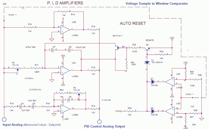
The Measured Value and the Setpoint are two inputs to a control system. The Measured Value is the amplified input from a transducer or sensor for a specific parameter that requires regulation, such as pressure or temperature. The Setpoint...

Most homes today have at least a few infrared remote controls, whether for the television, video recorder, stereo, etc. Despite this, many people have experienced frustration with lights that remain on after settling into a comfortable chair to watch...
This Atmel integrated circuit operates at a clock frequency of 12 MHz, facilitating communication between an infrared receiver and a personal computer. This setup enables the processing of signals by infrared receiver software, such as Girder. When a valid...
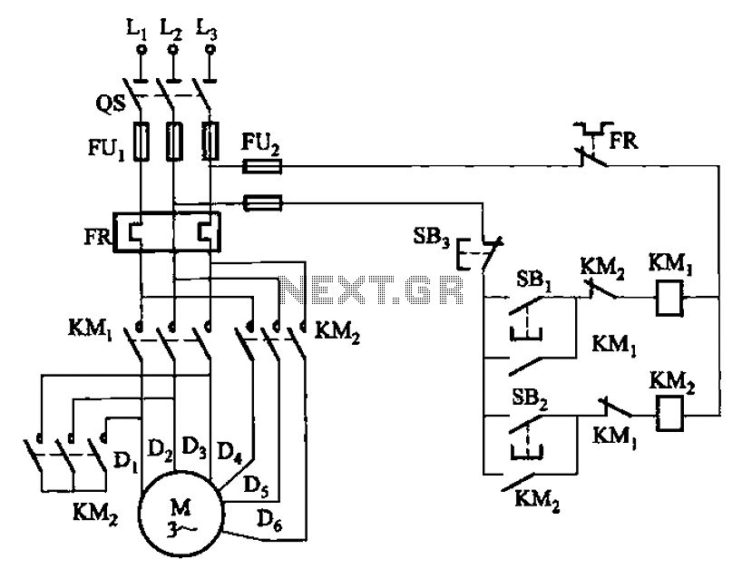
The circuit illustrated in Figure 3-97 features two contacts and is designed specifically for a 2kW dual-speed motor. In this configuration, SB1 is utilized for low-speed operation, while SB2 serves as the high-speed run button. The circuit operates by allowing...
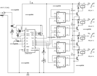
The following circuit illustrates a DTMF Remote Domestic System Control Circuit Diagram. Features: DTMF signals can be transmitted over a radio to control various domestic appliances. The DTMF (Dual-Tone Multi-Frequency) Remote Domestic System Control Circuit utilizes DTMF signaling for remote...