
On-off Infrared Remote Control

After the signal is inverted by T1, the pulses from this receiver trigger IC2a, a D flip-flop configured in monostable mode, with its output Q fed back to its reset input via R4 and C3. The pulse generated at the output Q of IC2a causes IC2b to change state, resulting in the LED within IC3 turning on or off. This circuit employs an opto triac with zero-crossing detection, enabling the system to switch without generating noise. It effectively triggers triac T2, which is connected to the load being controlled. The selected triac model can handle up to 3 amperes, although a more powerful triac can be used if necessary.
To minimize size and cost, the circuit is powered directly from the mains using capacitor C5, which must be a class X or X2 model rated for 230 volts AC. This type of capacitor, known as 'self-healing,' is the only suitable choice for power supplies connected to ground. Traditional capacitors rated at 400 volts do not provide adequate safety guarantees in this context. Given that the setup connects directly to the mains, it must be housed in a completely insulated enclosure. A power outlet model is effective for interposing between the grounded wall outlet and the remote control device.
This setup responds to any infrared signal, making it compatible with any remote control. However, it may also inadvertently respond to normal use of other remotes, which could be undesirable. To mitigate this issue, it is recommended to obscure the infrared receiver window as much as possible, ensuring that the remote control must be aimed directly at it to activate the system.
The overall design emphasizes safety and functionality, providing a user-friendly solution to a common household inconvenience. The integration of the D flip-flop and opto triac components ensures reliable operation, while the choice of capacitors and housing materials adheres to safety standards for devices interfacing with mains electricity. This circuit can significantly enhance the home entertainment experience by allowing users to control lighting with any infrared remote, thereby improving comfort and convenience during movie viewing.Most homes today have at least a few infrared remote controls, whether they be for the television, the video recorder, the stereo, etc. Despite that fact, who among us has not cursed the light that remained lit after we just sat down in a comfortable chair to watch a good film This project proposes to solve that problem thanks to its original app
roach. In fact, it is for a common on/off switch for infrared remote controls, but what differentiates it from the commercial products is the fact that it is capable of working with any remote control. Therefore, the first one you find allows you to turn off the light and enjoy your movie in the best possible conditions.
The infrared receiver part of our project is entrusted to an integrated receiver (Sony SBX 1620-52) which has the advantage of costing less than the components required to make the same function. After being inverted by T1, the pulses delivered by this receiver trigger IC2a, which is nothing other than a D flip-flop configured in monostable mode by feeding back its output Q on its reset input via R4 and C3.
The pulse that is produced on the output Q of IC. 2A makes IC. 2B change state, which has the effect of turning on or turning off the LED contained in IC3. This circuit is an opto triac with zero-crossing detection which allows our setup to accomplish switching without noise. It actually triggers the triac T2 in the anode where the load to be controlled is found. The selected model allows us to switch up to 3 amperes but nothing should stop you from using a more powerful triac if this model turns out to be insufficient for your use.
In order to reduce its size and total cost, the circuit is powered directly from the mains using capacitor C5 which must be a class X or X2 model rated at 230 volts AC. This type of capacitor, called self-healing`, is the only type we should use today for power supplies that are connected to ground.
Traditional` capacitors, rated at 400 volts, do not really have sufficient safety guarantees in this area. Considering the fact that the setup is connected directly to the mains, it must be mounted in a completely insulated housing.
A power outlet model works very well and can easily be used to inter-space between the grounded wall outlet and that of the remote control device. Based on this principle, this setup reacts to any infrared signal and, as we said before, this makes it compatible with any remote control.
On the other hand, it has a small disadvantage which is that sometimes it might react to the normal` utilization of one of these, which could be undesirable. To avoid that, we advise you to mask the infrared receiver window as much as possible so that it is necessary to point the remote control in its direction in order to activate it.
🔗 External reference
Related Circuits
A teleremote circuit enables the switching on and off of appliances through telephone lines. It can be used to control appliances from any distance, overcoming the limited range of infrared and radio remote controls. The circuit can switch up...
Having to use the infrared remote control, we will procure in addition to modulate the Nutchip infrared receiver. Do not let the name fool you, because more than one module component that looks like a large transistor. We use...
The objective of this project is to design a circuit for an electronic infrared communication system, develop innovative ideas for implementing this circuit, and study the circuitry along with various components such as DTMF generators, DTMF decoders, operational amplifiers,...
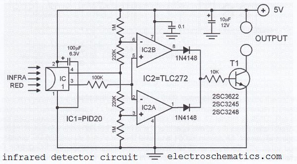
This infrared detector circuit utilizes a passive infrared detector component, PID20, which converts heat radiation into electrical impulses. The output voltage of the PID20 increases when an object approaches, provided that the object is warmer than the surrounding environment....
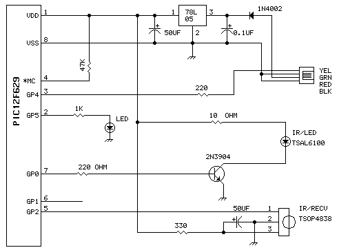
This unit uses one TSAL6100 IR/LED emitter from Digi-Key. This IR diode has a narrow (10 degree) radiation pattern at 940 NM. It is driven via 2n2904 transistor for maximum current pulses. The detector is a Vishay TSOP4838 38Khz...
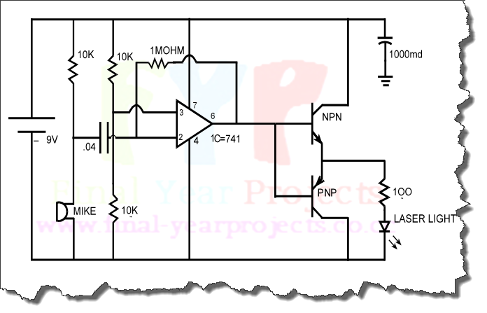
Integrated-circuit U1-an LF351 or 741 op amp-is used as a comparator to control the light. Resistors R2 and R3 provide a reference voltage of about 2.5 volts at pin 3 of U1. When daylight falls on light-dependent resistor LDR1,...