
Blinker Indicator

The described circuit utilizes a NAND gate (IC1) to manage the reset pulse for a counter mechanism, which is responsible for sequentially illuminating a series of LEDs. The counter increments its count each time the lamp is turned off, triggering a reset that allows the counting process to restart. The adjustment of the display's progression rate is achieved through the use of potentiometer P1, providing flexibility in how quickly the LEDs cycle through their illumination sequence.
The design ensures that only one LED is lit at a time, which serves to enhance visibility and manage power consumption effectively. The exception to this rule is the hazard blinker, which may illuminate multiple LEDs simultaneously for alert purposes. The brightness of the LEDs can be fine-tuned with resistor R12, allowing for user customization based on ambient lighting conditions or personal preference.
Furthermore, the circuit offers versatility in its component selection. By replacing standard diodes with LEDs, the circuit can be adapted to utilize LED technology, which may provide additional benefits such as lower power consumption and longer lifespan. In this modified configuration, the cathodes of the LEDs are connected to ground through resistor R12, maintaining the circuit's operational integrity while enhancing the visual output.
Overall, this circuit design presents a straightforward yet effective approach to managing LED displays, with adjustable parameters that cater to a range of user needs and preferences.When the lamp goes out, a new reset pulse is issued to the relevant counter by NAND gate IC1. A or IC1. B respectively, and the counter counts all the way up again. The progression rate of the display can be adjusted to the right speed using P1. Only one LED is on at a time (except for the hazard blinker). This allows the brightness to be easily adj usted using R12. Incidentally, the circuit can also be modified by replacing the normal diodes with LEDs, with all of the cathodes connected to ground via R12. Be the first of your friends to get free diy electronics projects, circuits diagrams, hacks, mods, gadgets & gizmo automatically each time we publish.
Your email address & privacy are safe with us ! 🔗 External reference
Related Circuits
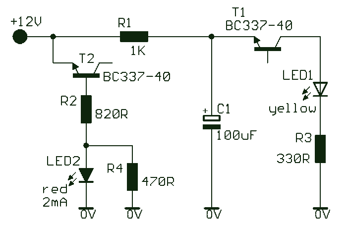
This simple and slightly odd circuit can clearly show the level of the supply voltage (in a larger device): as long as the indicator has good 12 volts at its input, LED1 gives steady, uninterrupted (for the naked eye)...
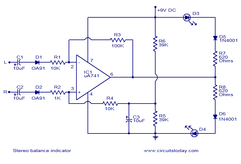
This is one of the simplest stereo balance indicator circuits available. The circuit provides a visual indication using two LEDs, which represent the difference in balance between the left and right channels of a stereo system. It is based...

This is a simple experiment involving a Light Dependent Resistor (LDR) and a CD4093 integrated circuit. It modifies a previous dark sensor project that utilized two transistors. In this configuration, when light falling on the LDR is obstructed, the...

The LED is normally lit, but it will be briefly extinguished if the input exceeds a preset level (set by RV1). A possible application is to monitor the output voltage across a loudspeaker; the LED will flicker with large...
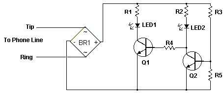
The circuit indicates that the phone is in use by illuminating a red LED. When the phone is not in use, a green LED lights up. It operates without requiring external power and can be connected at any point...

This project utilizes an AVR microcontroller as the first embedded systems project since college. The programming options were C and assembly, with assembly chosen due to familiarity and robust documentation in datasheets. Assembly provides a clear understanding of the...