
Peak level indicator
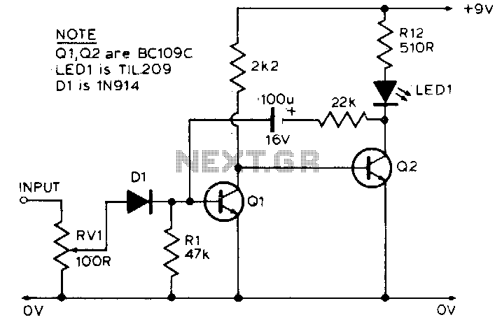
This circuit utilizes an LED as an indicator of voltage levels, specifically designed to respond to input signals that exceed a predetermined threshold. The LED remains illuminated under normal operating conditions, providing a visual indication of standard voltage levels. However, when the input voltage exceeds the threshold set by the variable resistor RV1, the LED will momentarily turn off. This behavior serves as an alert mechanism, signaling that the input signal has reached an excessive level.
In practical applications, one notable use of this circuit is in monitoring the output voltage across a loudspeaker. As audio signals fluctuate, the LED will flicker in response to large signal peaks, offering a visual representation of the signal's intensity. This flickering can help users identify potential distortion or clipping in the audio output, ensuring that the loudspeaker operates within safe limits.
The circuit typically consists of an LED, a variable resistor (RV1), and a voltage sensing mechanism, which may include a comparator or a simple transistor switch. The variable resistor allows for fine-tuning of the threshold voltage, accommodating various input signal characteristics. When designing the circuit, it is important to select components that can handle the expected voltage ranges and ensure that the LED is appropriately rated for the power it will dissipate.
Overall, this LED indicator circuit provides an effective and straightforward method for monitoring voltage levels in audio applications, enhancing the user's ability to maintain optimal performance and prevent damage to audio equipment.The LED is normally lit, but it will be briefly extinguished if the input exceeds a preset (by RVl) level A possible application is to monitor the output voltage across a loudspeaker; the LED will flicker with large signals. 🔗 External reference
Related Circuits
The water tank overflow liquid level sensor alarm circuit is a straightforward electronics project suitable for school students. Previous discussions have covered numeric water level indicators and water level controller circuits, which are more complex and intended for engineering...
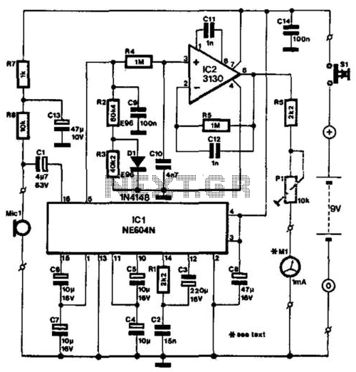
The NE604's signal-strength indicator section utilizes an internal logarithmic converter, allowing for a linear decibel scale. This feature enables the replacement of the moving-coil meter depicted in the diagram with a digital instrument. The assumed signal source is an...
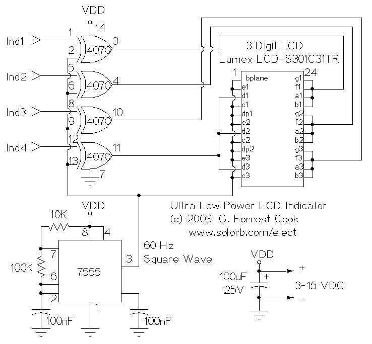
This circuit serves as an ultra-low power replacement for multiple LED on-off indicators. It also has the advantage of being easy to read in full daylight. With the parts shown, it is possible to display four bits of information....
Measuring radiation does not require expensive factory-made instruments. A simple device can be constructed using a radiation detector, such as the SBM-20 or a similar type. The circuit operates on 220 volts AC at 50/60Hz. The double-voltage rectifier circuit...
A simple water level sensor or liquid level detector for measuring or detecting a required level of water, liquid, or fluid in a tank, pool, well, aquarium, washing machine, etc. The water level sensor is an essential device utilized for...
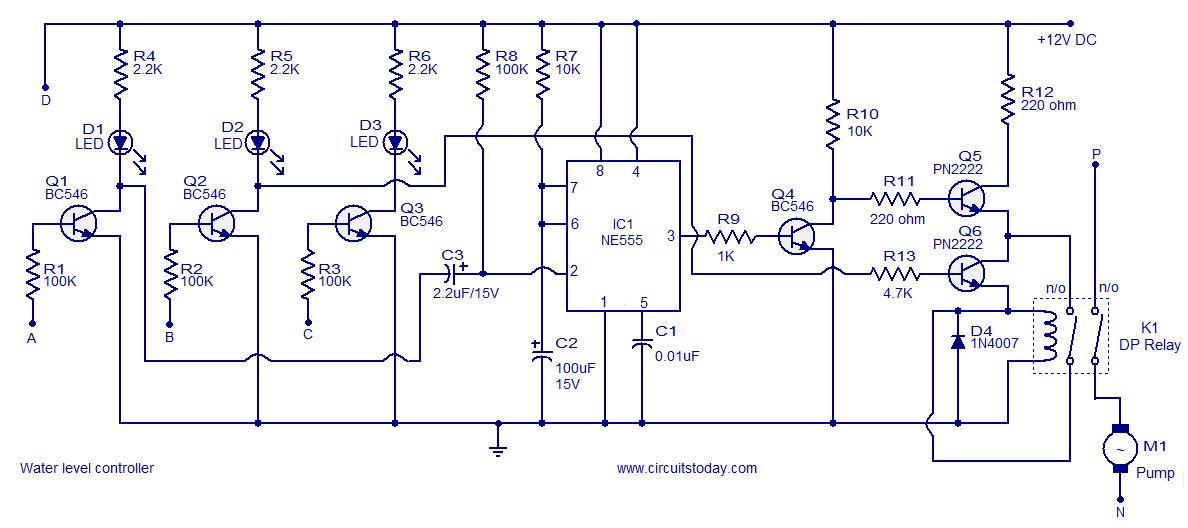
A simple water level controller circuit utilizing a 555 integrated circuit (IC) and six transistors. A relay is employed for controlling the pump motor. This water level controller circuit is designed to monitor and manage the water level in a...