
Morse Code Bicycle Safety Blinker

The schematic for this embedded system project is centered around the AVR microcontroller, specifically the ATTiny45. The microcontroller is programmed in assembly language, which allows for precise control over hardware operations, making it suitable for applications requiring detailed timing and interrupt handling.
The code begins with the inclusion of the microcontroller definitions file, which provides necessary constants and macros for the ATTiny series. The program starts at address 0x0000, where it establishes the reset vector and prepares the interrupt service routine for handling external interrupts on INT0 (Port B Pin 2). The use of `rjmp` instructions allows for efficient branching within the code, directing execution to the appropriate labels for reset and interrupt handling.
The initialization sequence is critical; it disables unnecessary peripherals to conserve power and sets up the data direction registers. The `DDRB` register is configured to define which pins are outputs and which are inputs. A pull-up resistor is enabled for the input pin connected to a momentary switch, ensuring reliable readings when the button is pressed. The output pin connected to an LED is configured for PWM operation, allowing for variable brightness control.
The global interrupt enable flag is set to allow the microcontroller to respond to external events. The interrupt service routine is designed to handle button presses, where a state machine toggles the LED on and off. The program utilizes delay routines to manage switch debounce and timing for the Morse code output.
In the main loop, the microcontroller continuously checks the state of the LED and manages the timing for Morse code signals. The use of subroutines for timing allows for modular code that can be reused for different timing requirements. The project showcases the capability of the AVR microcontroller to manage multiple tasks effectively while providing direct hardware control through assembly programming.
Overall, this project exemplifies the application of assembly language programming in embedded systems, highlighting the advantages of low-level control and efficient resource management in microcontroller applications.This is my first project using an AVR microcontroller and really the first embedded systems project I`ve done since college. I had two options for programming languages C and assembly. I chose assembly because I was familiar (at least with the 8051) and because it is well documented in the datasheets.
Another advantage of assembly is the ability t o know exactly what is going on especially when using a device simulator. ;Bikey Talkie ;by Tim Kyle. include "tn45def. inc" ;Includes the ATTiny45/65/85 definitions file. org 0x0000 ;Places the following code from address 0x0000 ;The Following instructions and "nop"s are for handling interrupts. rjmp RESET ;Take a Relative Jump to the RESET Label rjmp Interrupt0 ;Handle an interrupt input on INT0 or PortB Pin 2 (case pin 7) nop nop nop nop nop nop nop nop nop nop nop nop nop nop nop nop nop nop nop nop nop nop nop reti ;return from any other interrupts that might be thrown.
They are not important. Interrupt0: ldi r16, 0x10 ; this represents about 1/3 of a second for a dit rcall dah ; this produces a time delay long enough to handle switch bounce. ldi r18, 0x00 ; Zero reference (there are easier ways I know) cpse r18, r22 ; Was the unit on or off If equal (off) skip 1 instruction rjmp RESET pop r20 ;pop the old program counter from the stack.
It isn`t important. R20 is a convenient place to put it. sei ;Turn interrupts back on rjmp LOOP RESET: ;Reset Label ;Turn off all unnecessary clocks, timers, etc ldi r16, 0x0F out PRR, r16 ;The momentary button is connected to DIP pin 8 (INT0, Port B Pin 2). It should normally be pulled up. ;The LED is connected directly between pin 3 (Port B pin 4) and Vcc. PWM replaces the resistor. ldi r22, 0x00 ; Tell the interrupt process that the light is currently off. sei ; set Global Interrupt Enable ;A high in the DDRB means we will use the pin for output, zeros will configure the pin for input.
;Unused pins will be configured as outputs to avoid unnecessary interrupts being thrown. ;Pin7 Pin6 Pin5 Pin4 Pin3 Pin2 Pin1 Pin0 ; 1 1 1 1 1 0 1 1 = FB ldi r16, 0xFB out DDRB, r16 ;Store this value in The PORTB Data direction Register ;A high in the PortB register would enable the pull up resistor for an input pin. ;A high in the PortB register sets an output pin high. (in this case turning off the light) ;Pin7 Pin6 Pin5 Pin4 Pin3 Pin2 Pin1 Pin0 ; 0 0 0 1 0 1 0 0 = 14 ldi r16, 0x14 out PORTB, r16 ;GIMSK is the global interrupt mask.
ldi r16, 0x40 ;Enable INT0 Interrupt out GIMSK, r16 ;Enable INT0 Interrupt ;MCUCR Register ;00100001=21 ; ;7 BODS - R/O Brown Out Detector during Sleep (page 38) ;6 PUD - Pull up disable (page 55, 57) ;5 SE - Sleep Enable (Page 39) Set right before power down and unset right after power up. ;4 SM1 -Sleep Mode (page 39) ;3 SM0 -Sleep Mode (page 39) ;2 BODSE - R/O Brown Out Detector Sleep Disable (page 38) ;1 ISC01 - Interrupt sense control ;0 ISC00 ; ;ISC ;00-Low Level Causes Interrupt ;01-Toggle Causes Interrupt ;10-Falling Edge ;11-Raising Edge ; ;SM ;00-Idle ;01-ADC Noise Reduction ;10-Power-down ;11-Reserved ;BODS PUD SE SM1 SM0 BODSE ISC01 ISC00 ; 0 0 1 1 0 0 0 0 = 30 ldi r16, 0x30 ;This is where the edge trigger for the interrupt and the sleep stuff is hiding.
out MCUCR, r16 sleep LOOP: ;Loop Label ldi r22, 0xff ; Tell the interrupt process that the light is currently on. ldi r16, 0x08 ; this represents about 1/3 of a second for a dit rcall dit rcall dit rcall dah rcall dah rcall dit rcall dit rcall space rcall dah rcall dah rcall dit rcall dit rcall dah rcall dah rcall space rjmp LOOP ;Subroutine Space.
Tim Kyle Rev 0. 1 ;Waits the amount of time necessary for an interword space ;Uses Registers R16, R17 courteously (restores their previous values before return) ;Uses Labels ;Requires: Wait Space: push r16 ;Save previous contents of R16 to the stack. push r17 ;Save previous contents of R17 to the stack. rcall WaitOff rcall WaitOff rcall WaitOff pop r17 pop r16 ret 🔗 External reference
Related Circuits
CrustCrawler develops and manufactures advanced walking robots and robotic accessories. CrustCrawler specializes in the design and production of innovative walking robots, which incorporate advanced technologies and engineering principles to achieve improved mobility and functionality. These robots are typically characterized by...
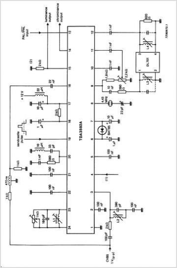
The TDA7541 is a high-performance tuner circuit with a stereo decoder designed for AM/FM car radios. It integrates a mixer, IF amplifier, demodulator for AM and FM, stereo decoder, quality detection, ISS filter, and PLL synthesizer with IF counter...
A rotary encoder generates two square wave outputs (A and B) that are 90 degrees out of phase. The number of pulses or steps produced per full rotation varies by model; for instance, the Sparkfun Rotary Encoder has 12...
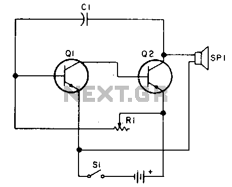
Oscillator, operates with 2 to 12 volts DC (optimal performance is achieved at 9 to 12 volts for maximum volume and clear keying). Additionally, R1 can be substituted with a 500K potentiometer, allowing the circuit to sweep across the...
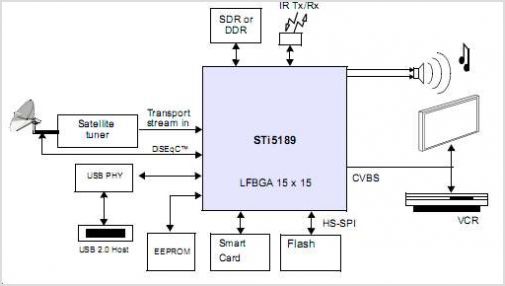
The STI5211 is a standard definition, full back-end processor designed for satellite set-top boxes, adhering to ATSC, SMPTE VC-1, DVB-S2, DIRECTV, DCII, and ARIB BS4 specifications. It delivers high performance for low-cost standard definition systems. Compared to the STi5202,...
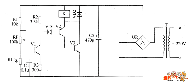
The optical safety switch circuit includes a power supply circuit, a light control circuit, and a control implementation circuit (switch circuit). The power circuit is made up of a power transformer (T), a bridge rectifier (UR), and a filter...