
bluetooth circuit in mobile phones
The Bluetooth circuit operates by utilizing a series of interconnected components that facilitate wireless communication. At the core of the system is the Bluetooth transceiver module, which integrates both the transmitter and receiver functionalities in a compact IC. This module requires a stable power supply, typically sourced from the main battery of the mobile device, ensuring that it operates efficiently during data transmission and reception.
The data flow within the Bluetooth circuit begins at the Bluetooth antenna, which captures incoming RF signals and transmits outgoing signals. The RF transceiver processes these signals, converting them to a digital format that can be handled by the application processor. The application processor is responsible for executing the software that manages Bluetooth connections, handles data packets, and interfaces with other applications on the mobile device.
The RF clock signal, which synchronizes the operations of the Bluetooth module, is critical for maintaining the timing of data transmissions. It ensures that packets are sent and received at the correct intervals, thereby minimizing errors and maximizing the reliability of the connection. Troubleshooting Bluetooth issues often begins with verifying the integrity of the power supply and the RF clock signal, as these are fundamental to the proper functioning of the entire system.
The circuit schematic diagram serves as a valuable tool for technicians, providing a visual representation of how each component is connected. This diagram allows for easy identification of critical points within the circuit, such as the voltage supply and RF clock, which are essential for effective troubleshooting. By following the schematic, technicians can trace signals through the circuit, identify faulty components, and implement repairs or replacements as needed.
In summary, the Bluetooth circuit in mobile phones is a complex integration of various components that work together to enable wireless communication. Understanding the layout and operation of these components is crucial for effective troubleshooting and repair, making the circuit schematic an indispensable resource for technicians in the field.Bluetooth is an open wireless device technology standard for exchanging data over short distances from fixed and mobile devices(using short wavelength radio transmissions), creating personal area networks (PANs) with high levels of security. The Bluetooth baseband protocol is a combination of circuit and packet switching. Slots can be reserved for synchronous packets. Each packet is transmitted in a different hop frequency. A packet nominally covers a single slot, but can be extended to cover up to five slots. Bluetooth can support an asynchronous data channel, up to three simultaneous synchronous voice channels, or a channel, which simultaneously supports asynchronous data and synchronous voice. Since we are talking about mobile phones here, it is much more really great to know how really bluetooth circuit works on cell phones circuit Isn`t it nice to know, so that we can easily managed how to fix it since it is our main reason in this tutorials by learning how to repair damaged cell phone devices.
In mobile phones Bluetooth problems also occurs when the bluetooth circuit is damaged, Some new cell phone techie find it hard to fix bluetooth for not knowing how the circuit works. Okay, lets tackle it for a while in just very simple explanation so that all of those without any background in electronics might can catch up too, and then we can use it in our everyday job on GSM field.
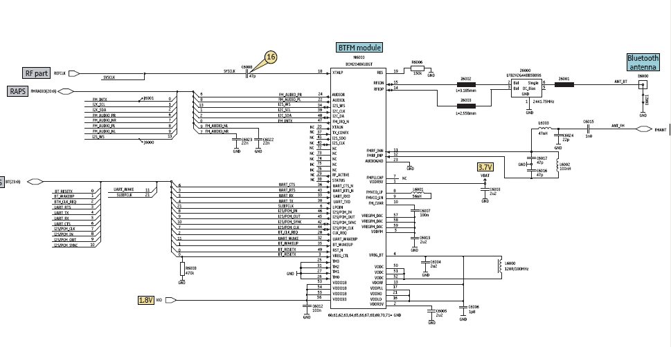
Figure the bluetooth circuit block diagram below for it shows how the Bluetooth Circuit works according to each corresponding parts or components that is being connected to it. The bluetooth transceiver module is packed into chip or IC (integrated circuit), this chip needs a certain power supply to make it work.
All the data that has been transmit (send) and receive from the bluetooth antenna and bluetooth RF (radio frequency) transceiver is feeds in for receiving and feeds out when sending to the application processor (cpu IC). There is an RF clock which comes from the RF circuit section is also feeds into it, that certain RF - Radio frequency is also needed by the bluetooth module to make it fully functional.
Since all those certain parts on bluetooth circuit were packed only into chips. A way to truly understand how does the circuit connect with each other from each certain components is by reading the circuit schematic diagram to locate this certain components parts on the main PCB board so that we can be able to check, trace and fix when a bluetooh failure happens. here`s an example of the bluetooth schematic diagram and figure out how each components connect with other.
In this method you can easily identify where that certain parts connected from one another. See here: You`ll notice that all of the bluetooth components is mounted in one section and near to each other. Some important spots is being labeled for quick troubleshooting guide. Like this picture below, the voltage supply and the RF clock are being labeled for quick check up and test procedures.
The key reason with this is that when it comes fixing bluetooth problem issues is to check the supply voltage and the RF clock signal first before trying to check, test, replace any other corresponding components being connected within the whole bluetooth circuit. 🔗 External reference
Related Circuits
Power an RS232-TTL converter circuit using the serial port to eliminate the need for an external power supply. It has been noted that the DTR, RTS, and TD pins can facilitate this. Since the TD pin is already utilized...
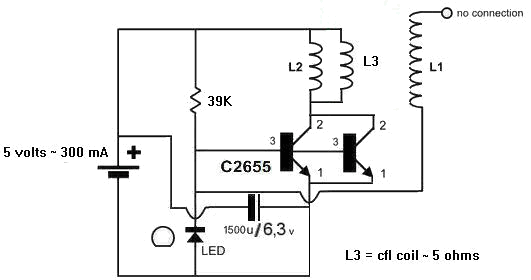
A 1N4148 diode and a 1-megohm resistor are included in the circuit. The inquiry pertains to how to power LED(s) using a 1.5-volt battery. There is also a question regarding the role of an additional coil, L3, and its...
To achieve optimal performance from an NBTV signal, it is crucial to utilize the complete dynamic range of the signal without any crushing at the black level or peak white. To evaluate the linearity of a video path, it...
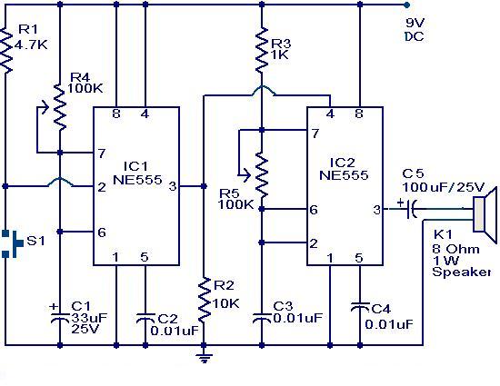
The primary component of this circuit is a doorbell utilizing two NE555 timer ICs. When the switch S1 is momentarily pressed, the speaker produces a bell sound, which is determined by the time period of the monostable multivibrator configured...
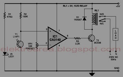
Typically, home appliances are controlled using switches, sensors, and similar devices. However, physical interaction with switches can pose safety risks in the event of a short circuit. The circuit outlined here eliminates the need for physical contact to operate...
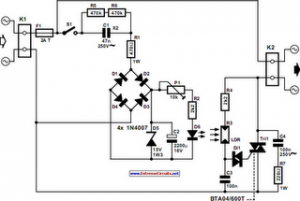
The following circuit illustrates an Automatic Light Dimmer Circuit Diagram utilizing a 1N4007 diode. Features include integration within a wall-mounted box. The Automatic Light Dimmer Circuit is designed to adjust the brightness of a light source automatically based on ambient...