
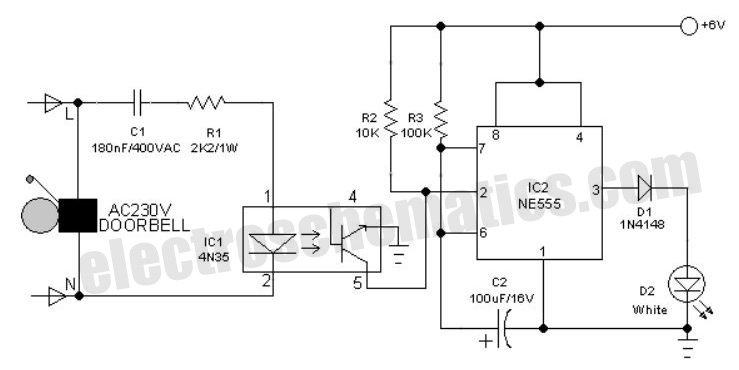
Doorbell circuit using NE555 IC
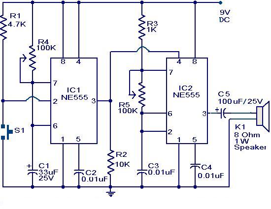
The circuit operates on the principle of two distinct configurations of the NE555 timer ICs. The first NE555 timer (IC1) is configured in monostable mode, which means it produces a single output pulse when triggered. This pulse duration is controlled by the resistor R4 and the potentiometer R5, which together define the time period for which the output remains high. The timing can be adjusted to suit various applications, providing flexibility in the duration of the bell sound.
When the switch S1 is pressed, it sends a low signal to pin 2 of IC1, activating the monostable multivibrator. The output at pin 3 goes high for the time period determined by the RC time constant formed by R4 and R5. This output triggers the second NE555 timer (IC2), which is configured in astable mode. In this configuration, IC2 continuously oscillates between high and low states, generating a square wave signal that drives the speaker.
The frequency of oscillation of IC2 is influenced by the resistance values of R5, which is a potentiometer allowing for real-time adjustments to the frequency. This feature enables the user to modify the tone of the bell sound produced by the speaker, thus providing a customizable auditory signal. The interaction between the two timers allows for a distinct and adjustable doorbell circuit that can be tailored to individual preferences or requirements.
In summary, this doorbell circuit effectively utilizes the NE555 timer ICs in both monostable and astable configurations to create a versatile and adjustable bell sound, with user-friendly controls for both duration and tone.The main part of this circuit Doorbell two timer NE555 ICs. When someone hit the switch S1 momentarily, the speaker emits a sound of the bell, if the time period of the monostable multivibrator built around IC1. When the switch S1 pressed, IC1 is enabled in your pin 2 and pin 3 output is high for a period of time previously set by the values of R4
and POT POT R5. When ofIC1 restores the IC2 output is high and starts to swing to make a bell sound through the speaker. The IC2 is configured as an astable multivibrator whose oscillation frequency can be varied with the help of POT R5.
By adjusting the values of R4 and R5, changes in tone are possible 🔗 External reference
Related Circuits
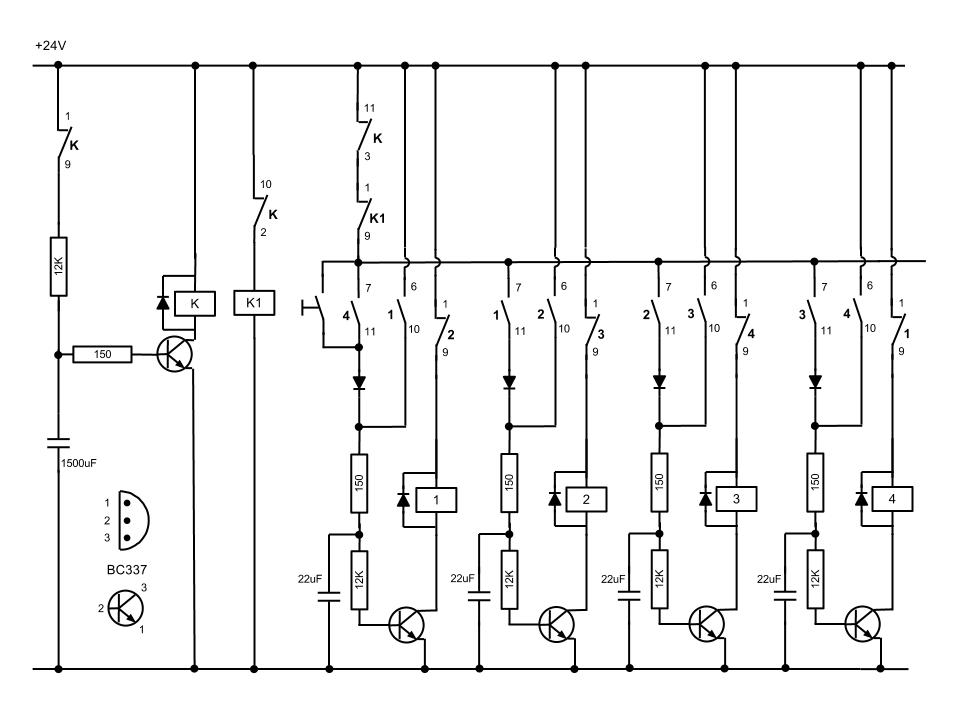
At the initial state, all pin 15 connections are grounded, causing resistor R0 to be energized. A 555 multivibrator generates a clock signal to IC1, activating the outputs from R0 to R8. This basic circuit can be employed to...
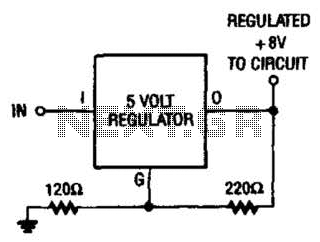
If locating an 8-V regulator proves difficult, a 5-V unit can serve as a replacement by connecting the regulator as illustrated here. In electronic circuits, voltage regulators are essential components that maintain a constant output voltage regardless of variations in...
The most challenging aspect of this circuit was determining its title. It can be easy to overlook the sound of a doorbell while watching television; this circuit addresses that issue by providing a visual indication, such as a lamp....
An interesting hobby circuit of a crank doorbell. The circuit is built around a 555 timer and a musical piezo buzzer. It operates using a 9-volt battery supply; a single 9-volt PP3/6F22 compact battery is sufficient to power the...
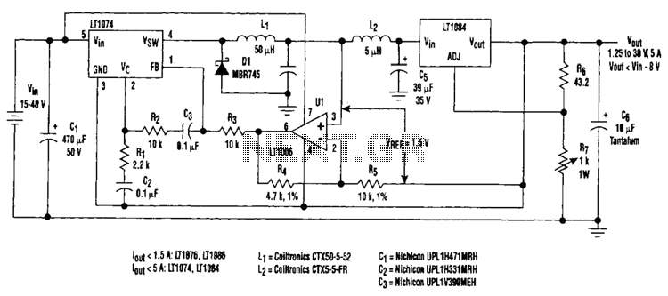
Large input-to-output voltage differentials, caused by wide input voltage variations, reduce a linear regulator's efficiency and increase its power dissipation. A switching preregulator can reduce this power dissipation by minimizing the voltage drop across an adjustable linear regulator to...
A schematic diagram for a broadband QRP SWR metering circuit intended for use in a QRP antenna tuner. The circuit allows the user to press a momentary DPDT switch to observe an LED indicator while adjusting the capacitors of...
Warning: include(partials/cookie-banner.php): Failed to open stream: Permission denied in /var/www/html/nextgr/view-circuit.php on line 713
Warning: include(): Failed opening 'partials/cookie-banner.php' for inclusion (include_path='.:/usr/share/php') in /var/www/html/nextgr/view-circuit.php on line 713