
control relay with infrared circuit
The circuit operates on the principle of infrared light detection, providing a touchless control mechanism for various appliances. The IR LED1 continuously emits infrared light, which is typically invisible to the human eye. When a hand moves within the detection range, it interrupts the infrared beam, causing a change in the light intensity received by the phototransistor T1. This change is detected and processed by the operational amplifier (IC1), which is configured as a comparator. The output from IC1 is determined by the voltage levels at its inverting and non-inverting inputs.
The sensitivity of the circuit can be fine-tuned using the voltage-divider preset (VR1). Adjusting VR1 modifies the reference voltage at pin 2 of IC1, allowing for calibration based on environmental conditions or specific application requirements. This feature ensures that the circuit can adapt to varying levels of ambient light or distance of the hand from the IR LED1.
The transistor BC548 (T2) acts as a switch that controls the relay (RL1). When the output from IC1 goes high, it turns on T2, allowing current to flow through the relay coil. This energizes the relay, which closes its contacts and completes the circuit to the connected appliance. The relay serves as an isolating mechanism, ensuring that the low-power control circuit does not directly handle the high voltage of the appliance.
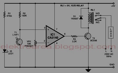
Overall, this circuit design provides a safe, efficient, and user-friendly solution for operating home appliances without the need for direct contact, significantly reducing the risk of electrical hazards.Normally, home appliances are controlled by means of switches, sensors, etc. However, physical contact with switches may be dangerous if there is any shorting. The circuit described here requires no physical contact for operating the appliance. You just need to move your hand between the infrared LED (IR LED1) and the phototransistor (T1). The inf rared rays transmitted by IR LED1 is detected by the phototransistor to activate the hidden lock, flush system, hand dryer or else. This circuit is very stable and sensitive compared to other AC appliance control circuits. It is simple, compact and cheap. Current consumption is low in milliamperes. The circuit is built around an IC CA3140, IRLED1, phototransistor and other discrete components. When regu lated 5V is connected to the circuit, IR LED1 emits infrared rays, which are received by phototransistor T1 if it is properly aligned.
The collector of T1 is connected to non-inverting pin 3 of IC1. Inverting pin 2 of IC1 is connected to voltage-divider preset VR1. Using preset VR1 you can vary the reference voltage at pin 2, which also affects sensitivity of the phototransistor. Op-amp IC1 amplifies the signal received from the phototransistor. Resistor R3 controls the base current of transistor BC548 (T2). The high output of IC1 at pin 6 drives transistor T2 to energise relay RL1 and switch on the appliance, say, hand dryer, through the relay contacts.
The working of the circuit is simple. 🔗 External reference
Related Circuits
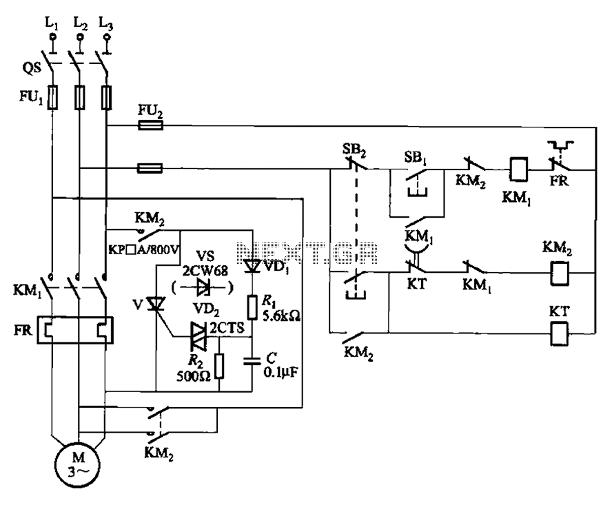
The circuit illustrated in Figure 3-148 eliminates the requirement for a step-down transformer by utilizing a thyristor for brake control in small capacity asynchronous motor braking applications. Upon shutdown, the contactor KM1 releases, while contactor KM2 engages the brake...
This circuit demonstrates that microprocessors, PCs, and modern ultra-accurate Digital-to-Analog Converters (DACs) are excessive for controlling four relays in sequence based on a control voltage ranging from 2.4 V to 12 V. By utilizing equal resistors in a ladder...
This is a highly sensitive envelope detector designed for AM radio applications. The circuit, illustrated in Figure 1, enables linear detection of weak signals with a modulation depth of 80-85%. The first stage (VT1) functions as a common-emitter amplifier...
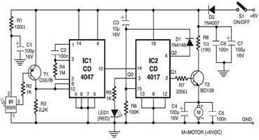
The following circuit illustrates an infrared toy car motor controller. This circuit is based on the 4047 and 4017 integrated circuits (ICs). Features: 16V. The infrared toy car motor controller circuit utilizes two primary integrated circuits, the 4047 and the...
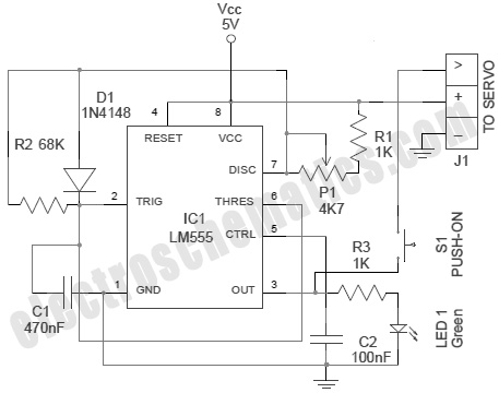
A servo is an error-sensing feedback control mechanism used to correct the performance of a system. A servo motor is a DC motor equipped with a servo mechanism. A servo motor is an electromechanical device that utilizes a closed-loop control...
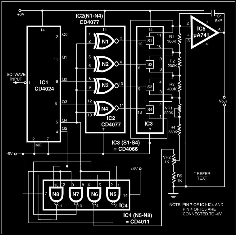
Many electronic devices rely on the shape of signals. Generating square wave signals from sine waves is relatively straightforward, while the reverse process is more challenging. The static square wave-to-sine wave converter circuit can produce an accurate sine wave...