
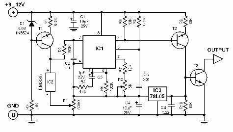
Voltage-to-Pulse Duration Converter
The Voltage-to-Pulse Duration Converter circuit utilizes a timer IC, typically the 555 timer, configured in monostable mode. In this configuration, the timer generates a pulse of a specified duration in response to a triggering voltage input. The duration of the output pulse is determined by the resistor and capacitor values connected to the timer.
An operational amplifier is employed to condition the input voltage signal. The OP Amp can be configured as a comparator to compare the input voltage against a reference voltage. When the input voltage exceeds the reference level, the OP Amp output triggers the timer IC, initiating the pulse generation.
In designing the circuit, it is essential to select appropriate resistor and capacitor values to achieve the desired pulse duration. The relationship between the pulse width (T) and the RC network can be described by the formula T = 1.1 * R * C, where R is the resistance in ohms and C is the capacitance in farads.
The operational amplifier's gain settings may also need adjustment to ensure proper triggering of the timer IC. Additionally, power supply considerations are critical, as both the OP Amp and timer IC require stable voltage levels for accurate operation.
Overall, this circuit is useful in applications where voltage levels need to be translated into time-based signals, such as in digital communication systems or pulse-width modulation (PWM) applications.This is a circuit of Voltage-to-Pulse Duration Converter. This circuit is used to convert voltage into pulse duration by combining a timer IC and an OP Amp 🔗 External reference
Related Circuits
The LTC1046 is a 50mA monolithic CMOS switched capacitor voltage converter. It serves as a replacement for the ICL7660/LTC1044 in 5V applications where higher output current is required. This device is optimized for high current capability with input voltages...
In battery-powered applications such as cell phones, PDAs, and digital cameras, an integrated DC-DC converter circuit solution provides multiple advantages regarding cost, size, and design complexity. A significant challenge in achieving a fully integrated solution is designing the frequency...
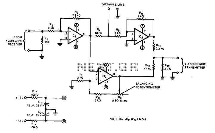
This audio converter circuit maintains 40 dB of isolation between the two halves of entry and exit of a four-line system while allowing a line connection between the two systems. A balancing potentiometer, R, adjusts the gain of the...
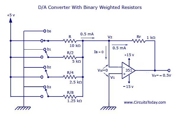
A digital-to-analog (D/A) converter utilizing binary-weighted resistors is illustrated in the accompanying figure. In this circuit, the operational amplifier (op-amp) is configured in inverting mode, although it may also be arranged in non-inverting mode. The schematic represents a 4-bit...
In certain temperature measurement applications, converting the measured value into a frequency rather than a voltage offers distinct advantages. A temperature-to-frequency converter can be directly interfaced with a frequency counter or connected to a computer without necessitating an A/D...
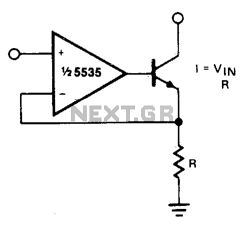
The output current is Iqut = Vin/R. For negative currents, a PNP transistor can be utilized, and for improved accuracy, a Darlington pair may be substituted for the transistor. With careful design, this circuit can be employed to control...