
booster radio fm schematic circuit
The FM booster circuit operates by amplifying weak radio frequency signals, making it possible to receive distant FM broadcasts with clarity. The core component, the 2SC2570 transistor, is a VHF/UHF transistor known for its high frequency and low noise characteristics, which are essential for effective radio signal amplification.
The common-emitter configuration is chosen for its ability to provide significant voltage gain, which is crucial for boosting weak signals. The circuit typically includes a tuned circuit that helps select the desired frequency while rejecting unwanted signals. This is achieved through the use of inductors and capacitors that form a resonant circuit, ensuring that the amplifier is tuned to the frequency of the FM station being received.
The assembly of the circuit on a glass-epoxy PCB is recommended due to its durability and superior insulating properties, which help maintain signal integrity. The input and output trimmers (VC1 and VC2) are variable capacitors that allow for fine-tuning of the circuit's performance. Adjusting these components optimizes the gain, ensuring the best possible reception of FM signals.
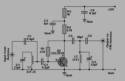
Overall, this FM booster circuit is a valuable tool for enhancing radio reception, particularly in areas where signal strength is weak. Proper assembly and tuning are critical to achieving the desired performance, making this circuit an effective solution for improving FM listening experiences.Here is a simple circuit of an FM booster that can be used to listen to programmes from distant FM stations clearly. This amplifier will pull in all distant FM stations clearly. The circuit is configured as a common-emitter tuned RF pre-amplifier wired around VHF/UHF transistor Q1.
2SC2570. (Only C2570 is annotated on the transistor body. ) Assembl e the circuit on a good-quality PCB (preferably, glass-epoxy). Adjust input/ output trimmers (VC1/VC2) for maximum gain. 🔗 External reference
Related Circuits
A simple 3-way crossover, intended for triamping Hi-Fi systems. This is a conventional 12dB / Octave unit, and cannot be expected to have the same performance as a Linkwitz-Riley aligned filter network. It will still be a vast improvement...
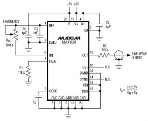
A high-frequency waveform generator is highly beneficial for electronic experimentation and design. This circuit generates sine wave oscillations; however, it can be modified to produce triangle or square wave functions. The frequency can be controlled using current. By disconnecting...
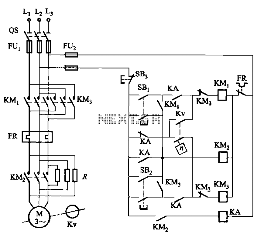
The circuit shown in Figure 3-129 is the C650-2 lathe brake control circuit, utilizing a speed control relay. The C650-2 lathe brake control circuit is designed to manage the braking mechanism of a lathe machine effectively. This circuit incorporates a...
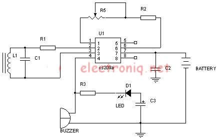
Metal detector schematic circuit using CS209A and a few electronic components. The metal detector circuit utilizing the CS209A integrated circuit is designed to detect metallic objects through the principle of electromagnetic induction. The CS209A is a specialized IC that facilitates...
The circuit is capable of measuring frequencies ranging from 1.5 kHz to 500 kHz by connecting different capacitors, C1 to C6. It can handle a maximum frequency of up to 1 MHz. Transistor T1 serves as the integrator, with...
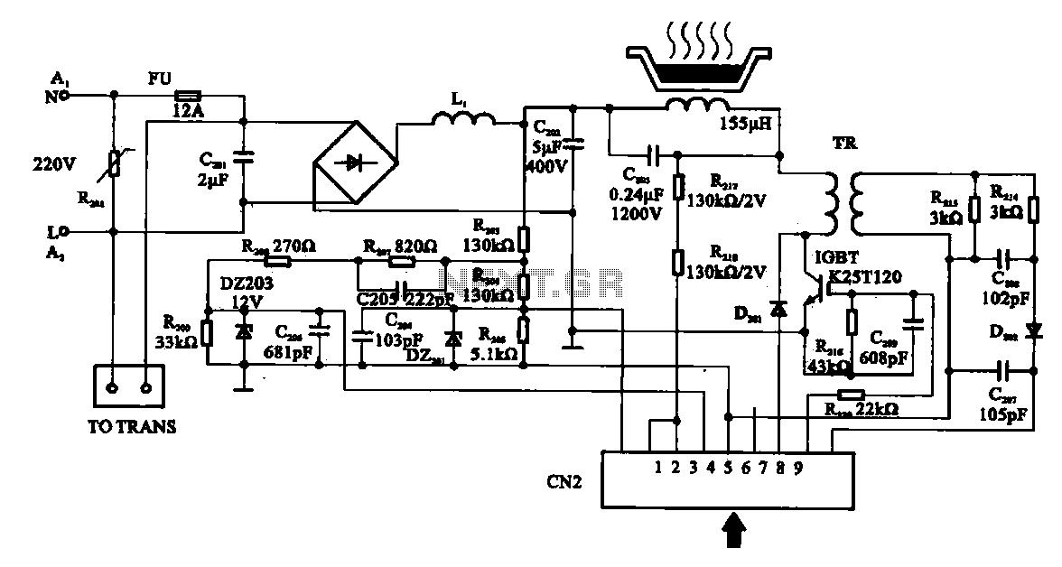
Cooker detection control circuit. The control circuit is designed for testing cookers. The inductance coil disc lesion typically measures around 150 µH. The stove plate coil and capacitor resonate with device C203. When resonating, the voltage generated across C203...