
Metal detector schematic circuit using CS209A
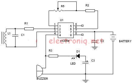
The metal detector circuit utilizing the CS209A integrated circuit is designed to detect metallic objects through the principle of electromagnetic induction. The CS209A is a specialized IC that facilitates the detection and processing of signals generated by the presence of metal.
The circuit typically consists of several key components: a power supply, the CS209A IC, an oscillator circuit, a search coil, and an audio output device such as a speaker or buzzer. The power supply provides the necessary voltage and current for the operation of the circuit, usually in the range of 5V to 12V.
The oscillator circuit is critical, as it generates a high-frequency signal that is transmitted through the search coil. The search coil is a loop of wire that creates a magnetic field when current flows through it. When a metallic object enters this magnetic field, it induces eddy currents in the metal, which in turn create their own magnetic field. This interaction alters the original signal from the oscillator, which is then picked up by the CS209A.
The CS209A processes the received signal and determines whether it corresponds to the presence of metal. If metal is detected, the IC activates the audio output device, providing an audible alert to the user. This alert can be adjusted in volume or tone, depending on the design of the circuit.
Additional components may include resistors and capacitors to filter signals and stabilize the circuit, as well as potentiometers for tuning sensitivity and discrimination between different types of metals. The layout of the circuit should be designed to minimize noise and interference, ensuring reliable operation in various environments.
In summary, the metal detector circuit using the CS209A combines several electronic components to create a functional and effective device for detecting metal objects, leveraging the principles of electromagnetism and signal processing.Metal detector schematic circuit using CS209A and few electronic components 🔗 External reference
Related Circuits
The electronic pest-killing lamp circuit comprises an oscillator, control circuit, high voltage generator, LED indicator circuit, and power supply circuit. The schematic diagram illustrates these components. The oscillator circuit includes a time-base integrated circuit (IC), resistors R5 to R7,...
This circuit demonstrates a dynamic AC signal level display drive, which can be utilized for audio level display purposes. The AC signal detection and drive control are achieved using the BA6124 integrated circuit, along with five external colored light-emitting...
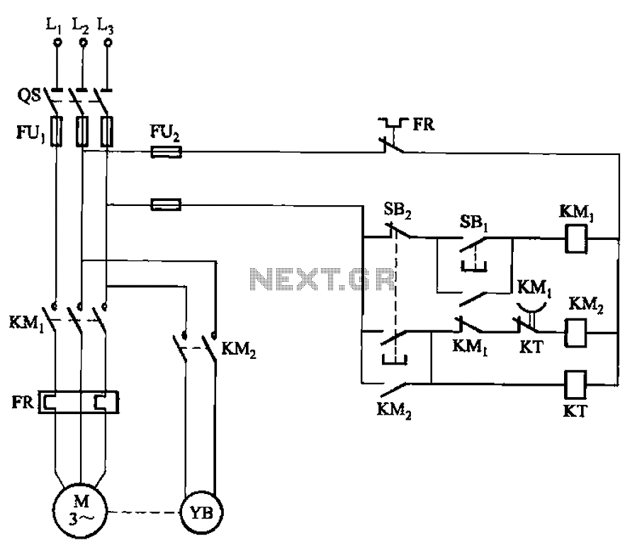
The circuit illustrated in Figure 3-123 operates as follows: When the stop button SBz is pressed, contact KMi releases, cutting off power to the motor. Simultaneously, KMz is activated, engaging the electromagnetic brake YB to hold the motor in...
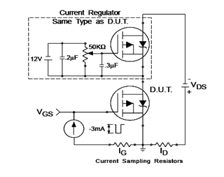
The IRF9540N Gate Charge Test Circuit is illustrated in the diagram below. The IRF9540N is recognized as a rectifier device that employs advanced processing techniques to attain an exceptionally low on-resistance per unit area, as stated in the datasheet....
An increasing number of appliances draw a very small current from the power supply. If designing a mains-powered device, one can generally choose between a linear and a switch-mode power supply. However, when the appliance's total power consumption is...
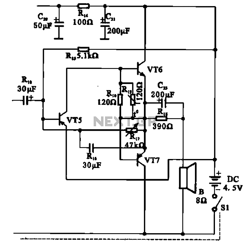
The transistor radio features a common output transformerless (OTL) power amplifier circuit. The VT5 component serves as the bias resistor for the driver stage. VT6 and VT7 form a complementary symmetry configuration, with VT6 being a germanium NPN transistor...