
brakelight flasher pcb
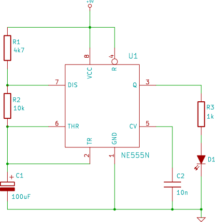
The circuit operates using the 555 timer IC, which is widely recognized for its versatility in timing applications. In this configuration, the 555 timer is set up in astable mode, allowing it to continuously oscillate between high and low states, thus producing a square wave output. The output pin (pin 3) of the 555 timer is connected to a relay or transistor that controls the bulb. The relay or transistor acts as a switch, enabling the higher current required by the bulb to be managed safely without overloading the 555 timer.
The frequency of the oscillation is determined by the values of two resistors (R1 and R2) and a capacitor (C1) connected to the 555 timer. The formula for calculating the frequency (f) of the output is given by:
f = 1.44 / ((R1 + 2 * R2) * C1)
In this setup, VR1 serves as one of the resistors, allowing the user to adjust the resistance and, consequently, the flashing rate of the bulb. The capacitor C1 helps to set the timing intervals, and its value can also be adjusted to modify the duty cycle of the output signal.
The circuit can be powered by a standard DC power supply, ensuring that the voltage levels are appropriate for the 555 timer and the load (bulb) being used. Proper heat dissipation methods should be implemented for the relay or transistor to prevent overheating during operation.
In summary, this flasher circuit provides a practical solution for controlling a bulb's flashing rate, making it suitable for various applications, including decorative lighting, indicators, or alerts. The ability to adjust the flashing rate offers flexibility for different user requirements.This is basically a flasher circuit modified to turn on and off a bulb instead of a LED. It uses a 555 timer IC working as an astable multivibrator. The flashing rate can be varied from very fast to a maximum of once in 1. 5 sec by varying the preset VR1. 🔗 External reference
Related Circuits
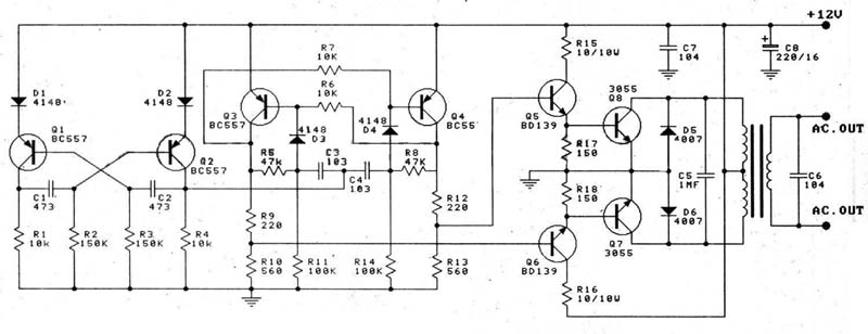
A 12V car battery is recommended as the input for this circuit, utilizing the 2N3055 transistor as the amplifier. This configuration can deliver a power output of up to 100W, making it suitable for use in battery chargers, emergency...
This is a 220V LED flasher circuit designed as a reliable alternative to thermally activated switches used for flashing Christmas tree lamps. It is a cost-effective and easy-to-assemble circuit. The components include R1 (100K), R2 (1K), R5 (1K), R3...
The connection point for the positive terminal of the 9V battery is represented as a circle at the end of a line labeled "+9V." This indicates where to apply power to the circuit. The 0V or "GND" of the...
The chip in the center with small bullet holes is likely proprietary. It is possible to salvage a few components from it, although understanding the circuit is not necessary for this purpose. Additionally, it is confirmed that the device...

Buffers are a specific category of amplifiers, and power buffers are a subset of power amplifiers. The defining characteristics of all buffers include unity gain and a low impedance output, ideally accompanied by low distortion. When examining commercially available...

This circuit is a 100W DC inverter based on a transistored multivibrator and serves as a transistor signal amplifier. The inverter converts a 12V DC input voltage to approximately 220V AC. It is recommended to use a 12V car...
Warning: include(partials/cookie-banner.php): Failed to open stream: Permission denied in /var/www/html/nextgr/view-circuit.php on line 713
Warning: include(): Failed opening 'partials/cookie-banner.php' for inclusion (include_path='.:/usr/share/php') in /var/www/html/nextgr/view-circuit.php on line 713