
100W DC Inverter Circuit with PCB Design
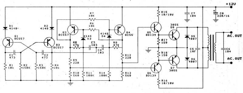
The 100W DC inverter circuit employs a transistored multivibrator configuration, which is essential for generating the necessary square wave signal required for the inverter's operation. The multivibrator consists of two 2N3055 transistors configured in a push-pull arrangement. This configuration allows for efficient switching, enabling the inverter to convert the low-voltage DC input into a higher voltage AC output.
The circuit begins with the connection of a 12V DC power source, typically a car battery, to the input terminals. The 2N3055 transistors are biased appropriately to operate in their active region. The output from the transistors is fed into a transformer, which steps up the voltage from 12V DC to approximately 220V AC. The transformer also plays a crucial role in isolating the output from the input, ensuring safety during operation.
To enhance performance, additional components such as resistors and capacitors may be included in the circuit. These components are used for stabilizing the multivibrator operation and filtering out any noise that may affect the output waveform. The inclusion of a feedback mechanism can also improve the efficiency of the inverter by ensuring that the transistors switch correctly and maintain the desired output voltage level.
This inverter is versatile and can be utilized in various applications, including powering small household appliances, providing backup power during outages, or charging batteries. Its ability to deliver up to 100W makes it suitable for light loads, while ensuring that it remains compact and efficient in design. Proper heat dissipation measures, such as heat sinks for the 2N3055 transistors, should be considered to prevent overheating during prolonged use.
Overall, this 100W DC inverter circuit is a practical solution for converting low-voltage DC power into high-voltage AC power, suitable for a wide range of electronic applications.This is the 100W DC inverter build based transistored multivibrator as well as transistor signal amplifier. The inverter will convert 12V DC voltage in the input and increase the voltage level to become about 220V AC.
12V car battery is recomended to be used as the input, transistor 2N3055 is used as the amplifier. It will deliver the power output up to 100W and you can use this inverter for battery charger, emergency light and other electronic appliances. 🔗 External reference
Related Circuits
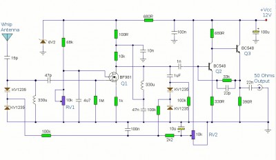
This is a booster antenna circuit designed for frequencies ranging from 550 kHz to 1650 kHz, aimed at amplifying signals received from a telescopic antenna. It covers the medium waveband within this frequency range. To drive low impedance (50...
A 2 µF capacitor is charged to approximately 340 volts, and the discharge is controlled by a silicon-controlled rectifier (SCR). A Schmitt trigger oscillator (74C14) and a MOSFET (IRF510) are utilized to drive the low-voltage side of a small...
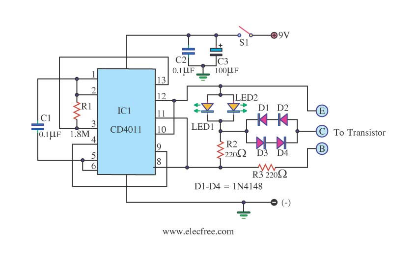
This is a transistor tester integrated into a circuit or printed circuit board (PCB). It is utilized when a project does not function correctly, allowing for the testing of electronic components. The transistor tester is a crucial tool in electronic...
This article presents a high reliability 1200V High Voltage Integrated Circuit (1200V HVIC) for half bridge driver applications, aimed at reducing the IC's supply current by approximately 50%. The 1200V High Voltage Integrated Circuit (HVIC) is designed specifically for half-bridge...
This is a very simple circuit utilizing a 555 timer IC to generate a square wave of frequency that can be adjusted by a potentiometer. With values given, the frequency can be adjusted from a few Hz to several...
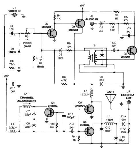
A simple TV audio-video transmitter circuit can be designed using this schematic diagram. This circuit can transmit video signals from a VCR or other devices to a TV without the need for cables. Video signals input at jack J1...
Warning: include(partials/cookie-banner.php): Failed to open stream: Permission denied in /var/www/html/nextgr/view-circuit.php on line 713
Warning: include(): Failed opening 'partials/cookie-banner.php' for inclusion (include_path='.:/usr/share/php') in /var/www/html/nextgr/view-circuit.php on line 713