
Bridge balance indicator
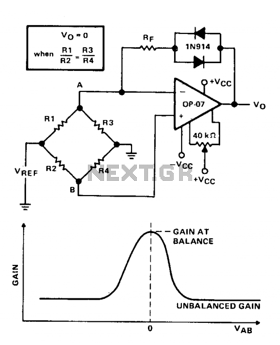
The circuit described utilizes a Wheatstone bridge configuration to compare two voltages with high precision. The primary function of the indicator is to measure the degree of balance between the two voltage sources. The Wheatstone bridge, while effective for larger voltage differences, can struggle to detect minor deviations from balance. This limitation is addressed by incorporating an operational amplifier (OP-07) that amplifies the voltage differences detected at the bridge's output.
The feedback loop includes two 1N914 diodes, which play a crucial role in enhancing the sensitivity of the circuit. These diodes are strategically placed to maintain high sensitivity around the null point, which is defined by the equality of the resistor ratios (R1/R2 = R3/R4). In an unbalanced state, the closed-loop gain of the amplifier can be approximated as Rp/r. Here, Rp represents the resistance in the feedback path, and r denotes the parallel equivalent resistance of Rl and R3, which influences the overall gain of the system.
The gain equation, G = RF(1/R1 + 1/R3), indicates how the feedback resistance (RF) and the values of resistors R1 and R3 affect the overall gain of the circuit. As the bridge becomes more balanced, the difference voltage V^, which is the output of the Wheatstone bridge, diminishes. This voltage is critical as it directly correlates to the output of the operational amplifier when amplified by the gain factor G.
When V^ approaches zero, the 1N914 diodes transition from a forward-biased state to a reverse-biased state, which leads to an increase in their resistance. This change in resistance raises the total feedback resistance, thereby increasing the circuit's gain. The result is a more accurate and sensitive detection of the balance condition of the bridge.
For visualization purposes, the output of the OP-07 can be monitored using a sensitive voltmeter or an oscilloscope, allowing for real-time observation of the voltage levels and the degree of balance achieved by the circuit. The circuit effectively demonstrates how feedback mechanisms can enhance the performance of basic measurement tools, providing precise readings even in scenarios where traditional methods may fail.Indicator provides an accurate comparison of two voltages by indicating their degree of balance (or imbalance). Detecting small variations near the null point is difficult with the basic Wheatstone bridge alone. Amplification of voltage differences near the null point will improve circuit accuracy and ease of use.
The 1N914 diodes in the feedback loop result in high sensitivity near the point of balance (R1/R2 = R3/R4). When the bridge is unbalanced the amplifier's closed-loop gain is approximately Rp/r, where r is the parallel equivalent of Rl and R3.
The resulting gain equation is G = RF(1/R1 + 1/R3). During an unbalanced condition the voltage at point A is different from that at point B. This difference voltage (V^), amplified by the gain factor G, appears as an output voltage, As the bridge approaches a balanced condition (R1/R2 = R3/R4), V^ approaches zero. As V^ approaches zero the 1N914 diodes in the feedback loop lose their forward bias and their resistance increases, causing the total feedback resistance to increase.
This increases circuit gain and accuracy in detecting a balanced condition. The figure shows the effect of approaching balance on circuit gain. The visual indicator used at the output of the OP-07 could be a sensitive voltmeter or oscilloscope. 🔗 External reference
Related Circuits
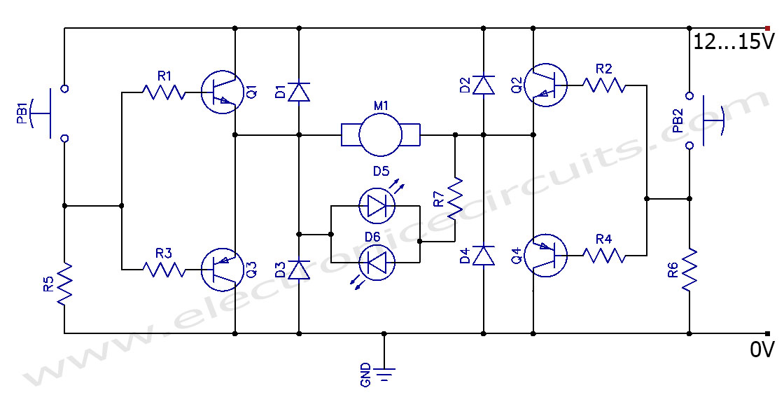
This circuit can control the direction of a DC motor, allowing it to operate in both clockwise and counterclockwise directions (forward and backward). The described circuit employs an H-bridge configuration, which is essential for reversing the polarity of the voltage...
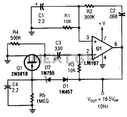
This Wien-bridge sine-wave oscillator utilizes a 2N3819 as an amplitude stabilizer. The 2N3819 functions as a variable-resistance element within the Wien bridge. The Wien-bridge oscillator is a type of electronic oscillator that generates sine waves. It employs a bridge circuit...
The circuit was designed to provide an indication before a 12 V lead-acid battery reaches a discharged state using an LM723 voltage regulator and a positive NPN standard voltage. The circuit utilizes the LM723 voltage regulator, which is well-suited for...

The classic Wien-Bridge oscillator, with incandescent lamp nonlinear stabilization, provides a low distortion sine wave source. A thorough and clear discussion of the Wien-Bridge oscillator is provided in Malvino's Electronic Principles. Using an inexpensive op-amp with sufficient bandwidth and...

These circuits could be used as the basis for Model Railroad DCC Boosters or PWM motor controllers. The first schematic is for a basic 3 Amp - DCC Booster using the LMD 18200 CMOS, H-Bridge. Included in the design...
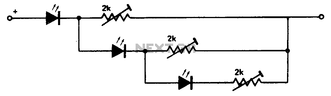
This circuit creates a compact level indicator suitable for situations where a traditional meter would be impractical or cost-prohibitive. The resistor values are contingent upon the type of LED utilized. For MV50 LEDs, resistor values of 2 kΩ are...