
Wien-Bridge Oscillator
The Wien-Bridge oscillator is a well-known circuit configuration that utilizes the principles of feedback and phase shift to generate sinusoidal waveforms. In this implementation, the use of an incandescent lamp as a nonlinear feedback element introduces a variable resistance that stabilizes the oscillations. As the amplitude of the output signal increases, the lamp's resistance increases, effectively reducing the gain of the feedback loop and preventing the circuit from saturating.
The circuit's design relies on the careful selection of components, particularly the op-amp and the lamp, to ensure that the oscillation frequency remains stable and within the desired range. The LM4562 op-amp is particularly well-suited for this application due to its high gain bandwidth product and fast slew rate, which are essential for generating high-frequency signals with low distortion.
The lead-lag network, which is critical in determining the oscillation frequency, is composed of resistors and capacitors that create the necessary phase shift for sustained oscillation. The precise values of these components must be calculated to achieve the desired frequency while maintaining the stability of the circuit.
In practical applications, the circuit can be tested and verified with various loads to ensure that it meets performance specifications. The ability of the LM4562 to drive capacitive loads and maintain output amplitude under varying conditions is a significant advantage, making it suitable for a range of audio and signal generation applications.
By modifying the feedback network, users can tailor the oscillator's output to suit specific requirements, whether for audio testing or other signal generation tasks, demonstrating the versatility and effectiveness of the Wien-Bridge oscillator design.The classic Wien-Bridge oscillator, with incandescent lamp nonlinear stabilization, provides a low distortion sine wave source. A thorough and clear discussion of the Wien-Bridge oscillator is provided in Malvino`s Electronic Principles.
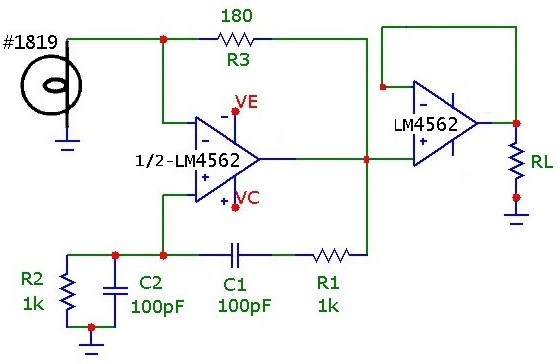
Using an inexpensive opamp with sufficient bandwidth and slew-rate, it is possible to nudge the oscillation fre quency of this classic circuit into the MHz range. The following simple circuit demonstrates a 1. 27 MHz Wien-Bridge oscillator. Although intended for use in ultra low noise/distortion premium audio applications, the National LM4562 opamp has sufficient bandwidth, slew rate (GBW: 55 MHz, SLR: 20 V/us) and output drive capability to provide decent MHz signal oscillation. At 1 MHz, in order to stay within the slew-rate limit, the circuit must be designed with an oscillation amplitude of less than 2Vp.
This can be achieved by proper selection of the incandescent lamp and feedback resistor. At the oscillation frequency, determined by the lead-lag network feedback transmission peak, the lamp resistance must be exactly half the feedback resistance. The lamp resistance, which increases with voltage, is determined by the RMS voltage across the lamp, so the voltage feedback network must satisfy this condition.
(As a guideline, it is useful to measure the DC resistance versus voltage of the lamp). Also the values must be within the current drive capability of the selected opamp. In addition, the output signal peak amplitude must be within the voltage range capability for the available Vcc/Vee supply. Fortunately, these conditions are easily satisfied with a little planning. In this example a #1819 lamp, nominally 28 V @ 40 mA was used. Using standard resistor values, an Rf of 180 ohm provides output oscillation at 1. 27 MHz with 1. 35 Vp amplitude, within the slew-rate limit. With a supply voltage of +_3. 0V, the LM4562 can operate within 0. 5V of the rails, and so the circuit can be conveniently powered using 4-AA cells as a split supply. The protoboard layout and overall test configuration are shown below (in this case powered by a split 8-AA supply although it does function identically with +_3.
0 V supply). The circuit oscillates at 1. 27 MHz as shown below, and is quite stable even at this relatively high frequency. The discrepancy in frequency is due to non-ideal opamp effects (discussed below) which shift the oscillation condition from the ideal zero-degree phase shift point of the lead-lag network and thus pulling the oscillation frequency to lower values. Since the negative feedback loop resistance is rather low, the drive capability of the opamp and output resistance will also shift the operating point.
Use of lamps with higher resistance values (e. g. #80, 327, 344, 1869, 2158, 7218 lamps) will provide greater feedback resistance and less current consumption, although in the present circuit, the output signal current draw is low by design at about 5 mA, well within the drive capability of the opamp. The LM4562 is a dual opamp so the Wien-Bridge can be easily coupled to a unity-gain buffer. In this configuration, a rock solid 1. 27 MHz test signal circuit can be implemented. The circuit below was tested under different loads RL, and the output amplitude and frequency were constant (Vout=1.
35 +-0. 01 Vp, f= 1. 27 +_0. 005 MHz) down to loads as low as and including 50 ohm (at which point the output current draw is Ip = 27 mA. roughly the limit of this opamp). Futhermore, this opamp can drive capacitative loads as high as 100 pF. With a 50 ohm resistive load AND a 3 ft. RG-58U test cable terminated into a 1 Mohm scope input (about 100 pF shunt capacitance), the 1. 27 MHz was unchanged. The circuit can obviously be used, with change of lead/lag network values, to generate extremely low distortion test audio signals in the 100 Hz to 20 kHz audio range as well as ultrasonic signals in the hundreds of kHz range.
It would be int 🔗 External reference
Related Circuits
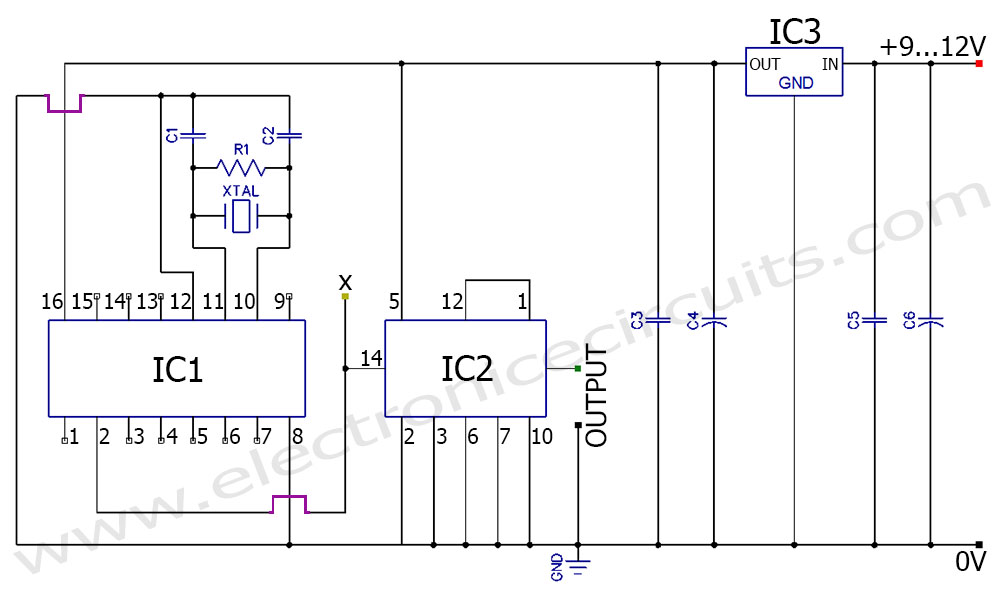
The FV-1 features internal circuitry that supports an external crystal, ideally a 32.768 kHz watch crystal. These crystals are very affordable and readily available. While other frequencies are available, they are not as cost-effective or common. If the system...
1 kHz RC phase shift oscillator circuit The 1 kHz RC phase shift oscillator circuit is designed to generate a continuous sine wave output at a frequency of 1 kHz. This circuit typically utilizes a combination of resistors and capacitors...
Free energy motors and generators are available for purchase, featuring plans for overunity devices. These devices resemble oscillators used in Joule thief circuits, although there may be some errors present in the designs. However, the concept remains clear. Free energy...
A frequency generator circuit capable of producing 50 Hz and 60 Hz outputs using a crystal oscillator. This oscillator can be utilized to generate precise frequency signals. This frequency generator circuit employs a crystal oscillator as its core component, which...
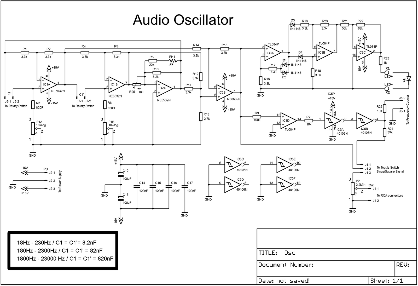
The project involves adding a DIY audio oscillator to a home workshop, which is essential for testing audio projects. While a basic oscillator is already available, it lacks a frequency counter. The design follows a schematic that provides a...
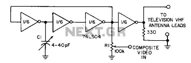
Three gates of a 74LS04 form the oscillator circuit. Capacitor C1 allows fine frequency adjustment to a specific television channel and helps stabilize the circuit. Potentiometer R1 acts as the mixing input and provides adjustment of the contrast ratio...