
DC Motor Clockwise Anticlockwise Control H-bridge Circuit
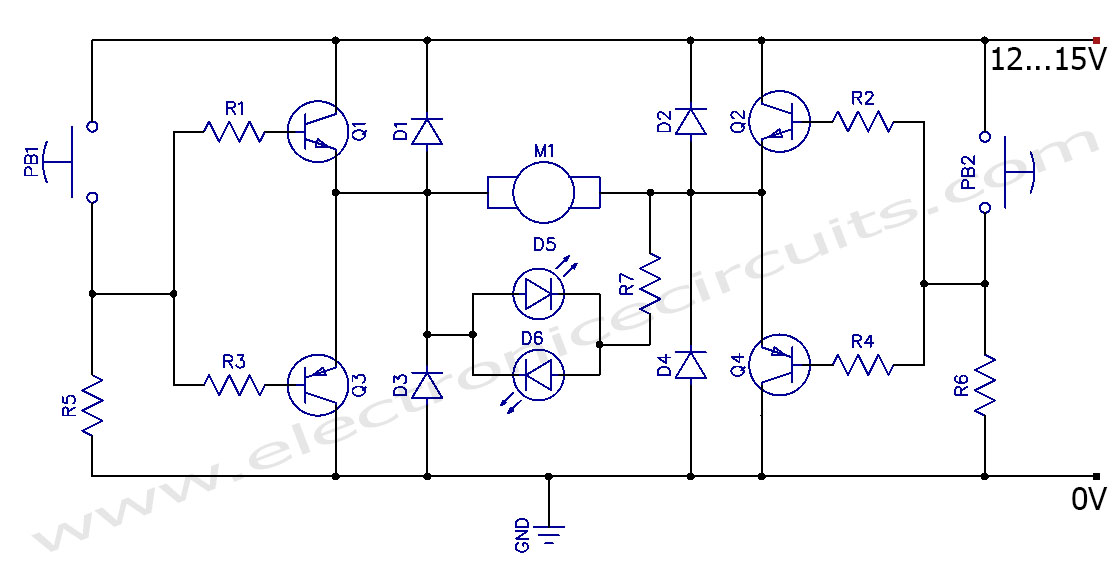
The described circuit employs an H-bridge configuration, which is essential for reversing the polarity of the voltage applied to the motor, thereby enabling bidirectional control. The H-bridge consists of four switches (transistors or MOSFETs) arranged in a bridge configuration. When two opposite switches are activated, current flows through the motor in one direction, causing it to rotate clockwise. Conversely, activating the other two switches reverses the current flow, resulting in counterclockwise rotation.
Control signals for the H-bridge can be generated using a microcontroller or a simple control circuit. For example, a microcontroller can provide PWM (Pulse Width Modulation) signals to modulate the speed of the motor in addition to controlling its direction. A push-button switch or a joystick can be used to manually change the direction of the motor, providing an intuitive interface for operation.
Protection features such as flyback diodes are often included in the design to prevent voltage spikes generated by the inductive load of the motor from damaging the control circuitry. Additionally, current sensing can be integrated to monitor the motor's load and prevent overheating or stalling conditions.
This bidirectional motor control circuit is widely used in various applications, including robotics, conveyor systems, and automated machinery, where precise control over motor direction and speed is required.This circuit can control direction of a DC motor. This can operate the motor in both directions (Bi-direction) Clockwise and Anticlockwise (forward and back) 🔗 External reference
Related Circuits
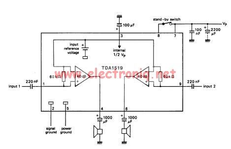
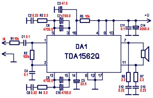
The TDA1519 circuit can deliver 2x6 watts output power. TDA1519 is an integrated class-B dual output amplifier in a 9-lead single in-line (SIL) plastic medium power package primarily developed for car radio applications. The TDA1519 is a robust integrated circuit...
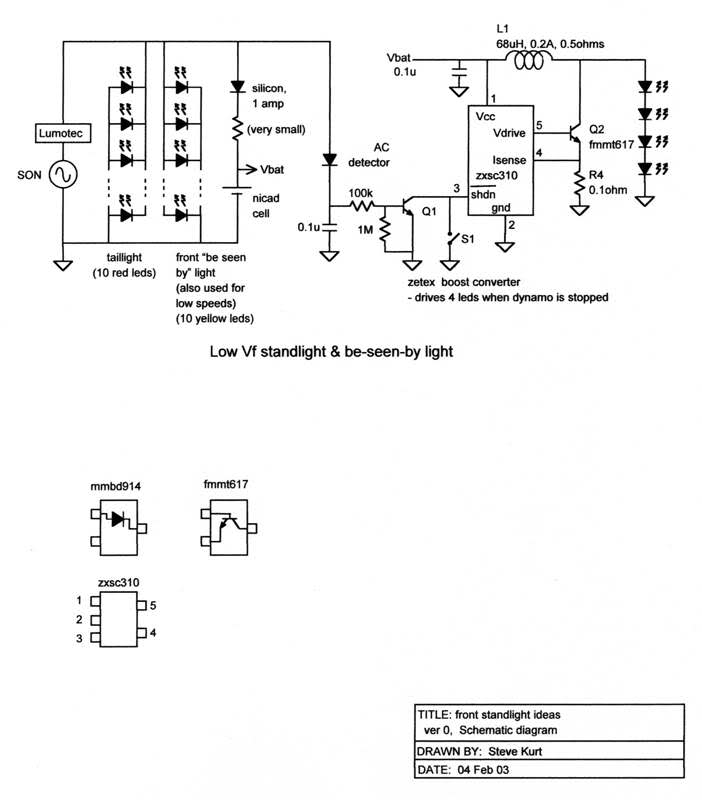
The resistors were not measured precisely, and given their ±5% tolerance, along with a Vref range of 1.2 to 1.3 volts, it is possible to exceed 6 volts in certain scenarios. A discussion arose regarding the effectiveness of these...
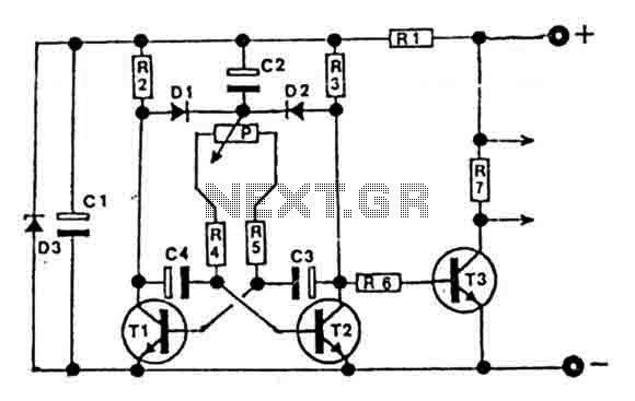
This circuit is designed for controlling motors, lamps, heating elements, and similar devices continuously from nearly zero to maximum capacity (5-95%). It utilizes impulse control for nearly lossless operation, providing almost total torque for motors. The transistor T3 must...
%2Busing%2Bop%2Bamp%2B741%2Bic%2B.png)
A zero crossing detector (ZCD) is a voltage comparator that switches its output between +Vsat and -Vsat (where Vsat is the saturation voltage, approximately 14V) when the input crosses the zero reference voltage. Comparators are fundamental operational amplifier circuits...
The integrated circuit LM386 is a low-power audio frequency amplifier that requires a low-level power supply, typically batteries. It is available in an 8-pin mini-DIP package. The IC is designed to provide a voltage amplification of 20 without the...
This is an LM338-based power supply that is uncomplicated and easy to construct. It has been in use for an extended period without any issues. The circuit lacks a current adjustment feature, which has been addressed by incorporating an...
Warning: include(partials/cookie-banner.php): Failed to open stream: Permission denied in /var/www/html/nextgr/view-circuit.php on line 713
Warning: include(): Failed opening 'partials/cookie-banner.php' for inclusion (include_path='.:/usr/share/php') in /var/www/html/nextgr/view-circuit.php on line 713