
Bridge circuit

The described circuit employs a transistor configured as an audio oscillator, which generates audio frequency signals. The audio transformer in the collector serves to couple the oscillator's output to the load, which in this case is the secondary winding of the transformer. This transformer plays a critical role in impedance matching and signal transfer between the oscillator and the audio output.
The linear potentiometer, connected to the secondary winding, allows for adjustable output levels. The slider of the potentiometer provides a variable resistance that can be manipulated to control the amplitude of the audio signal reaching the headphones. The relationship between the two sections of the potentiometer is determined by the values of Z1 and Z2, which represent the impedance values in the circuit. When no audio signal is present in the headphones, the ratio of the potentiometer's sections reflects these impedance values, ensuring that the circuit maintains a balanced output.
For practical implementation, the transistor should be selected based on its frequency response characteristics to ensure optimal performance as an audio oscillator. The audio transformer should also be chosen to match the frequency range of interest and the desired output impedance. Proper biasing of the transistor is essential to maintain its operation in the active region, thus allowing for consistent oscillation and audio signal generation. Additionally, consideration should be given to the power supply voltage and the overall circuit layout to minimize noise and interference, ensuring high-quality audio output.The transistor is connected as an audio oscillator, using an audio transformer in the collector. The secondary goes to a linear pot. The ratio between the two parts of the pot from the slider is proportional to the values of Z1 and Z2 when no signal is heard in the phones.
Related Circuits
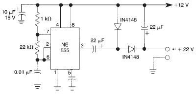
This voltage doubler circuit utilizes a 555 timer integrated circuit configured as an astable multivibrator. It can deliver a maximum output current of 50mA; exceeding this limit will result in a reduction of the output voltage. The actual output...

The circuit is constructed around a single integrated circuit (U1), specifically an MC3403P quad op-amp, three transistors (Q1-Q3), and several supporting components. It receives its input from the antenna (ANT1). The signal is processed through a high-pass filter composed...

An automatic cycle switch circuit utilizing a 555 integrated circuit (IC) as the control element. It incorporates a capacitive step-down circuit and employs a bidirectional thyristor to control relays or loads with specific on and off timing. The circuit...

The schematic represents a relatively simple transistor circuit. Analyzing such schematics evokes memories of college days spent studying electrical engineering. However, the complexity of the schematic can be daunting after a long time away from the subject. To refresh...

I decided to make a commercial surface mount PC board using the LED2 sensor concept. It is quite sensitive and can track to a few degrees of accuracy in bright sunlight. If a blocking shadow is used the accuracy...
The locator utilizes a transistor radio as the detector. By tuning the radio to a weak station, the capacitor C1 can be adjusted so that the locator's oscillator beats against the received signal. When the search head passes over...