
Need Help Deciphering Circuit Board Schematic
The circuit under discussion operates as a wire speed control system for a DC motor, typically used in welding applications. The main power source provides a voltage range of approximately 18.7 to 36.3 volts, which is regulated and conditioned before being delivered to the motor. The LM7812C voltage regulator was originally employed to provide a stable 12V output; however, it has been replaced with an MJE3055T NPN transistor to facilitate higher current handling capabilities required by the motor. This substitution is critical given the motor's power demands and ensures that the control circuit can manage the motor's operation effectively.
The circuit board's design includes a rectifier stage, which is unusual in a DC-only welder setup. This rectifier is likely implemented to ensure that any fluctuations in the input voltage are smoothed out, providing a consistent DC output to the motor. The presence of diodes, particularly those oriented to allow current flow in one direction, serves to protect the circuit from potential back EMF generated by the motor when it is turned off or when the load changes suddenly.
The diodes labeled as "black and silver" and "black and orange" are likely standard rectifier diodes, while the orientation of the other diodes must be confirmed to determine their function in the circuit. If they are Zener diodes, they may be used for voltage regulation or protection against overvoltage conditions.
The modifications made to the circuit, including the replacement of the MPF 102 with an MPS2222A transistor and the adjustment of the base and collector connections, indicate an effort to optimize the control signal to the motor. This change has reportedly improved the wire feed speed functionality, suggesting that the previous configuration may have been limiting the circuit's performance.
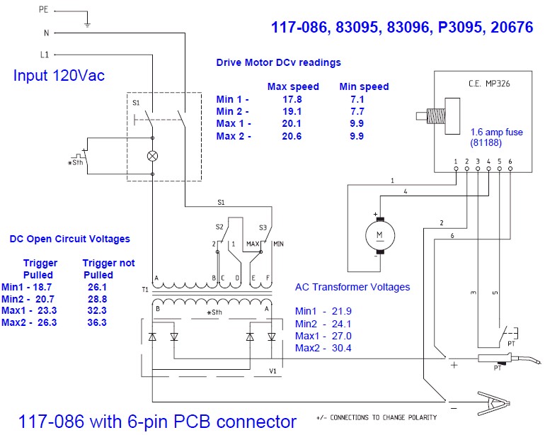
In summary, the circuit's design integrates various components to manage the operation of a wire speed DC motor effectively. The adjustments made to replace components and the inquiry into the schematic's functionality reflect a thorough approach to troubleshooting and optimizing the circuit for its intended application. Further testing will provide insights into the performance metrics, such as wire feed speed in inches per minute, which are critical for evaluating the system's overall efficacy.The wire speed DC motor is constantly receiving about 20 volts, regardless of the state of the switch on the nozzle handle. I checked the switch with an ohm meter. The switch works fine. I even disconnected the switch from the circuit board. The motor is still going. By looking at the physical circuit board, I have come up with the following schematic in EAGLE CAD, which I believe to be 99% accurate.
My friend replaced two components, one was in a TO-220 package, and the other was in a TO-92 package. At this time, he is unable to find the components he removed from the board, so it is anybody`s guess as to what they were.
The components that are in the circuit now are an LM7812C voltage regulator (the TO-220 package) and an MPF 102 601 N-channel RF amplifier (the TO-92 package). (In the schematic, I replaced both with standard NPN transistors. I have no idea if that makes any sense. ). There are also two "black and silver" diodes on the board, and two "black and orange" diodes on the board.
They are labeled as such on the schematic. That is the reason I`m posting. I need help deciphering this schematic, because it doesn`t make any sense to me. For instance, the welder is DC only, no AC side. So the line voltage comes into the welder, goes to the power switch, through a transformer, and then through the power diodes. The wire speed control circuit board is then connected here, to this rectified power. So why is there a rectifier on the circuit board Also, there are diodes towards the bottom of the schematic, which point up (i.
e. , allow flow from neg -> pos, but not pos -> neg (unless they`re Zener diodes. I`m not sure). I have included the schematic I made in PDF form, as well as a "semi-schematic" that I received from the manufacturer, as that is about all I can fit into 97KB. I need help to make sense as to how this thing is supposed to work. The voltage coming into the board is approximately 18. 7 - 36. 3 volts, and the voltage going to the DC motor is approximately 7. 1 - 20. 6 volts. I replaced the LM7812C with a proper TO-220 NPN transistor (MJE3055T, part number 276-2020 from RadioShack (they call it a TIP3055).
The trigger now works as it`s supposed to. I replaced the MPF 102 with a proper TO-92 NPN transistor (MPS2222A, part number 276-2009 from RadioShack). I also switched the base and the collector around, as suggested by Resqueline. The wire feed speed now appears to work correctly. I`ll have to run some wire and test what the wire feed speed is in inches per minute. 🔗 External reference
Related Circuits
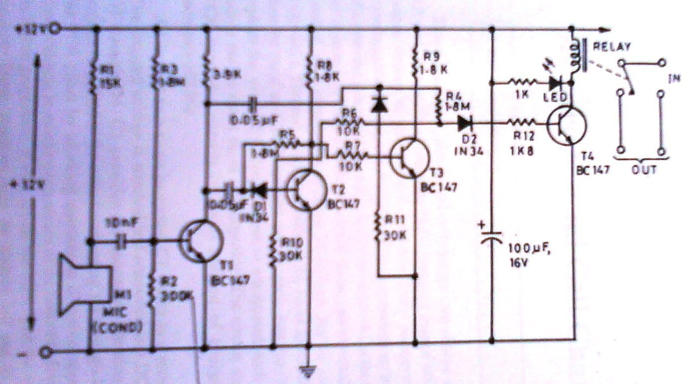
This clap switch can turn on and off a light, fan, music system, or alarm—virtually any gadget—at the sound of a clap. The most remarkable feature of this design is its ability to provide efficient two-state control without the...
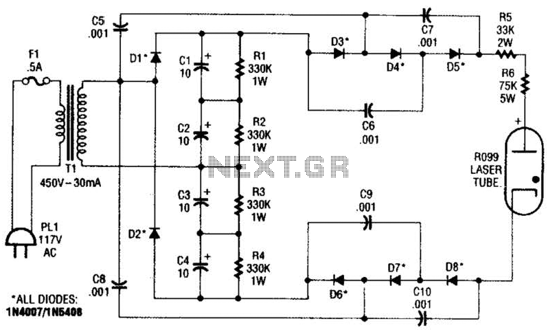
This supply generates an initial high voltage for ignition purposes. After ignition, the supply generates about 1300 to 1500 V. If a higher ignition voltage (than the 6000 V supplied) is necessary, more multiplier stages can be added to...
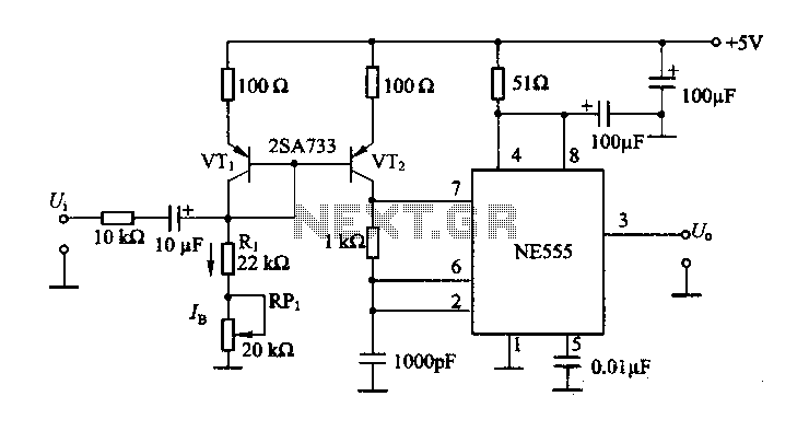
The circuit consists of a NE555 timer and a frequency modulation circuit that modifies the self-excited multivibrator NE555 by adjusting the charging current for frequency modulation. The components VT1 and VT2 form a current mirror circuit, which generates a...
The Johnson 275 watt and Kilowatt Matchboxes are often seen as exaggerated and unfairly criticized. They are neither exceptional tuners nor poorly designed. The main drawbacks include the fixed coupling link and the fact that they are balanced voltage...
The ICL7107 is a 3 1/2 digit LED analog-to-digital converter (A/D converter). It features an internal voltage reference, high-isolation analog switches, sequential control logic, and display drivers. The ICL7107 is designed to convert analog signals into digital representations with a...
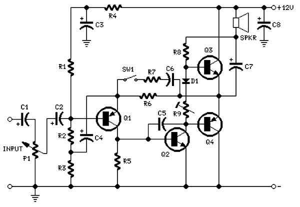
The circuit is intentionally designed using older type transistors to achieve harmonic distortion and to mitigate the challenges of sourcing high-quality components. The amplifiers can be easily powered by a plug-in wall transformer rated at 12V. When SW1 is...