
Brightness display circuit 555
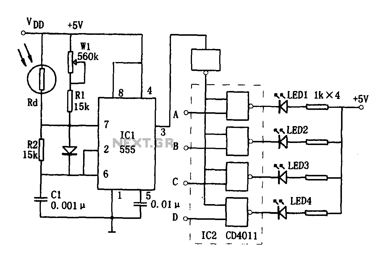
The brightness display circuit operates by utilizing a light-sensitive sensor that adjusts its resistance based on the ambient light levels. This sensor (Rd) is integrated into a multivibrator configuration that includes resistors (R1, R2, and variable resistor W1) and a capacitor (C1), controlled by a 555 timer. The 555 timer is configured in astable mode, generating a square wave output that varies in frequency depending on the light intensity detected by the sensor.
The oscillation period is crucial for determining the frequency of the output signal. The equations provided detail how the time constants (T_charge and T_put) are derived from the component values. As the light intensity increases, the resistance of Rd decreases, leading to a higher oscillation frequency. This results in a shorter T_charge, which in turn affects the duty cycle of the output waveform.
The duty cycle is an important aspect of the circuit, as it dictates the proportion of time the LED is turned on versus off. A decreased duty cycle indicates that the LED will be on for a shorter duration, contributing to a dimmer output. Conversely, as the light intensity decreases, the duty cycle increases, allowing for brighter LED illumination.
The outputs from the multivibrator are fed into the CD4011 integrated circuit, which acts as a NAND gate configuration. This IC processes the oscillation signals and drives the corresponding light-emitting diodes (LEDs) based on the modified duty cycle. The result is a dynamic brightness display that visually indicates the surrounding light levels, effectively translating environmental changes into a proportional LED brightness response.
The circuit design emphasizes the interaction between light intensity and electronic components, showcasing the principles of analog electronics in creating a responsive visual display. This application can be beneficial in various scenarios, such as automatic lighting systems, ambient light indicators, or decorative lighting that adjusts to environmental changes.As shown for the brightness display circuit. The circuit consists of light-sensitive sensor, an oscillation circuit, LED display circuit. Wherein the light-sensitive sensor that is photosensitive resistance Rd. Of the multivibrator Rd, R1, W1, R2, C1,555 composed. The oscillation period of kitchen charge + 7 = f women. Where T charge = 0.693R2C1, t put = 0.693 (Rw1 + R1) Rd / (Rw1 + R1 + Rd) C1. Due to changes in light intensity Rd with two Ju different resistance, so that the oscillation frequency f = 1 / T is changed, the oscillation waveform duty ratio D = t charge / T also changed. When the light intensity and oscillation frequency increases, the duty ratio becomes smaller, the oscillation signal and the corresponding end (A, B, C, D) through IC2 (CD4011) after driving the corresponding light emitting diode operating, the LED brightness increases.
Related Circuits
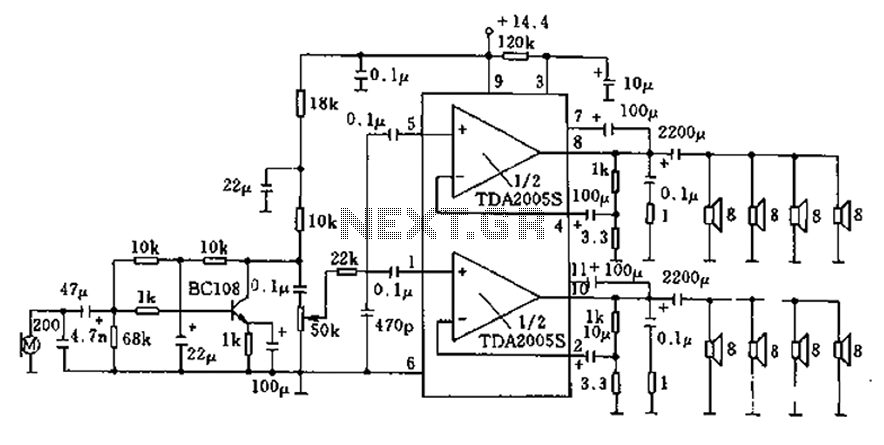
20W bus radio and megaphone circuit utilizing the TDA2005S double low-frequency power amplifier integrated circuit design. The front end can be connected to either a microphone input or a low-frequency radio output voltage amplification stage. Each TDA2005S provides 10W...
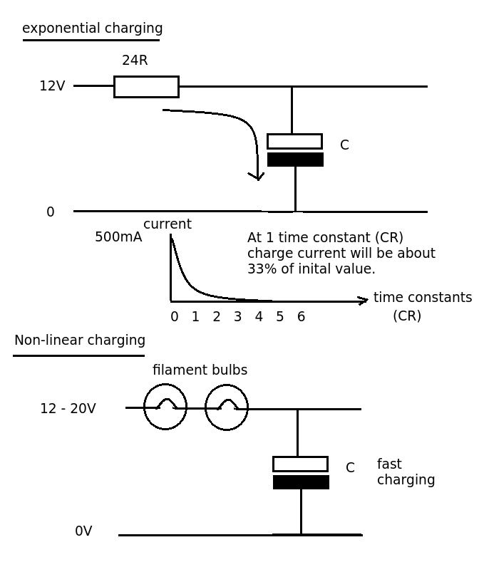
Designing a simple current limiter that charges a large 4.7mF capacitor with a charge current of approximately 500mA from a supply voltage of 10-20V. The dilemma is that there are existing MMBT2222A transistors available, which would be preferable to...
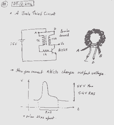
A simple voltage boost circuit known as the Joule Thief has been identified for construction. The Joule Thief is a minimalist boost converter designed to extract energy from low-voltage sources, such as depleted batteries, and increase the voltage to a...
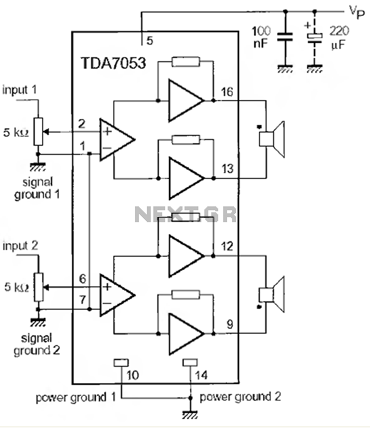
This is a 1-watt stereo audio amplifier circuit utilizing the TDA 7053 integrated circuit from Philips. It is specifically designed for battery operation, delivering 1 watt per channel from a 6V DC supply. The circuit operates optimally between 6V...

The MK484 AM radio circuit offers a comprehensive solution that includes an RF amplifier, detection, and automatic gain control (AGC) circuit. It requires only a few external components to achieve a high-quality AM tuner. The circuit features an input...

This system is compatible with 4-, 6-, or 8-cylinder automobiles. The timebase generated by IC5 functions as an oscillator that drives counter IC6, which divides the frequency by 6, 4, or 3 for 4-, 6-, or 8-cylinder engines, respectively....