
Transistor current limit circuit power handling
The circuit design involves a current limiting mechanism that ensures safe charging of the large capacitor while preventing excessive power dissipation in the transistors. The charging process begins when the supply voltage is applied, allowing the capacitor to charge at a controlled rate. The current limiter is primarily achieved through the use of the MMBT2222A transistor, which operates in its active region to regulate the current flowing into the capacitor.
To enhance the current handling capability, the additional 2N2222A transistor is introduced in parallel with the MMBT2222A. This configuration aims to distribute the total load current between the two transistors. However, careful consideration must be given to the characteristics of the transistors, as differences in current gain (hFE) can lead to unequal current sharing. To mitigate this risk, it is advisable to use resistors in series with the base of each transistor, which can help balance the base currents and improve current sharing.
The circuit also requires a robust design to manage the initial inrush current when the capacitor is charged. During this phase, the voltage across the collector can reach significant levels, necessitating the use of transistors that can withstand higher power dissipation. It may be beneficial to implement thermal management strategies, such as heat sinks, to prevent overheating of the transistors during operation.
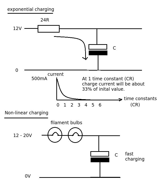
In summary, the design of this current limiter circuit emphasizes the importance of careful component selection and configuration to ensure reliable performance. The use of the MMBT2222A and 2N2222A transistors in parallel presents both opportunities and challenges, requiring a thorough understanding of their characteristics and behavior under load conditions. The overall goal is to achieve a safe and effective charging mechanism for the large capacitor while minimizing the risk of component failure due to excessive power dissipation.Designing a simple current limiter, which charges a large (4. 7mF) capacitor with a charge current of (roughly) 500mA from a supply voltage from about 10-20V - see the below circuit. My dilemma is that I already have a bunch of MMBT2222A and it would be nice to use this part without another line item.
Whilst it can happily push 500mA through t he collector, it only has a power rating of 350mW, which will be massively exceeded when the capacitor is first charged as the voltage across the collector will be about 10V and hence the power will be about 5W for the first 200ms or so. In the circuit above, I have added an extra 2N2222A in parallel (with the idea of adding more as required) with the existing one, but I feel this strategy if fraught with danger - mismatched gains will cause unequal currents and defeat the whole purpose of the exercise.
🔗 External reference
Related Circuits
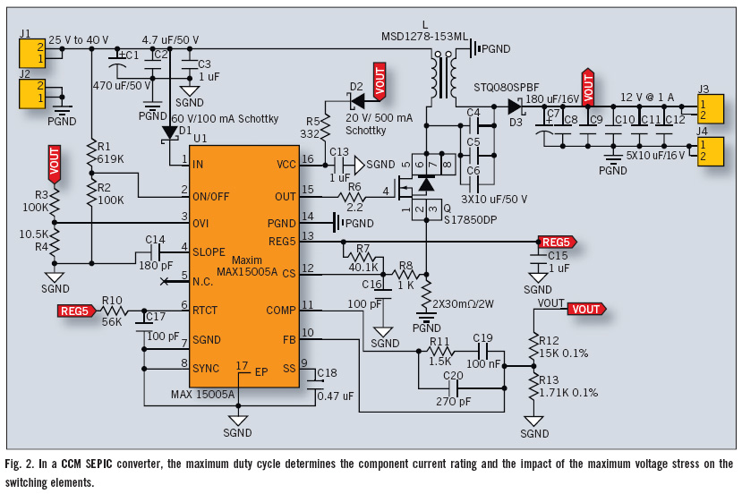
The Single-Ended Primary Inductance Converter (SEPIC) topology is an effective solution for automotive power systems that necessitate an output voltage that falls between the low and high values of the input voltage. The SEPIC topology is suitable for this...
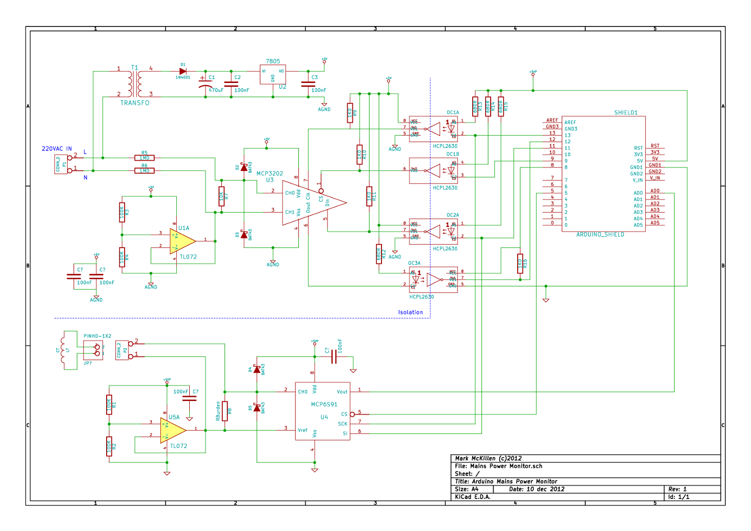
A mains (220-240VAC) power monitoring circuit has been sought for interfacing with an Arduino. While the OpenEnergyMonitor solution employs a transformer for isolation and measurement of mains voltage, it has been noted that the transformer does not couple effectively...
A simple audio amplifier with a 10 Vpp output designed for use with the AD633 ring modulation chip. The datasheet for the chip is available, and the circuit will utilize the XR2206 function generator IC for the modulation input....
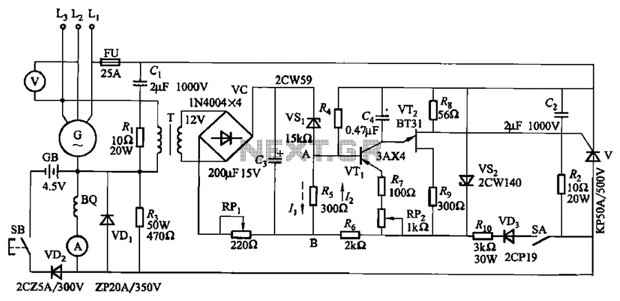
The circuit depicted in Figure 7-32 is designed for an excitation device capable of handling a terminal voltage of 400V and a capacity of less than 75kW for synchronous generator motors, enabling automatic adjustment of excitation. When the generator...
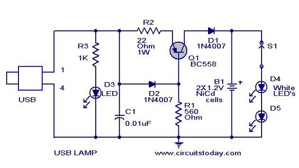
A simple USB LED lamp circuit utilizing a 5-volt power supply sourced from a USB port, designed to illuminate a desktop or laptop computer during power outages. The USB LED lamp circuit operates by converting the 5-volt DC power provided...
Here is a circuit diagram for adjusting the brightness of a light bulb. The second battery is utilized to power the circuit. This circuit can be used to modify the brightness of images during close-up photography with a digital...