
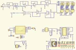
Digital Tachometer Circuitry
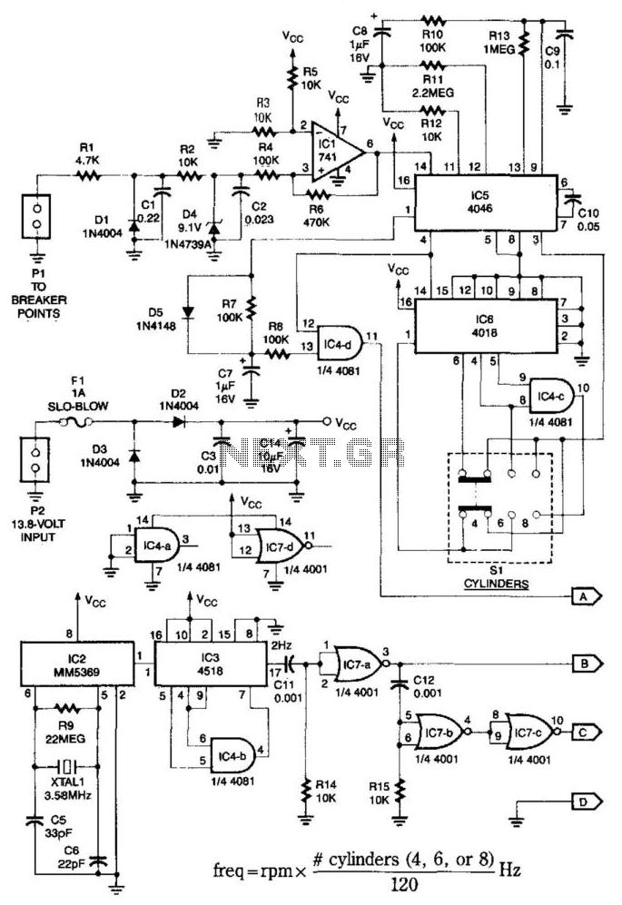
This system is designed to operate with various engine configurations, providing flexibility in automotive applications. The oscillator IC5 is crucial for generating a stable timebase, ensuring accurate frequency division for the different engine types. The selection switch S1 allows the user to easily configure the system for the engine in use, enhancing usability.
The phase-locked loop functionality of IC5 ensures that the output signal remains synchronized with the ignition system's frequency, which varies with engine speed. This synchronization is vital for maintaining accurate engine monitoring and performance metrics. The conditioning of the ignition signal by IC1 is essential for proper interfacing with the subsequent circuitry, ensuring that noise and other unwanted signals are minimized.
The output from IC4D is critical as it provides a frequency that is directly related to the engine's operational parameters. This frequency is then displayed in real-time, allowing for immediate feedback on engine performance. The generation of a 60-Hz signal by IC2, derived from a 3.58-MHz reference, showcases the use of frequency synthesis techniques to produce standard timing signals.
The division of the 60-Hz signal by IC3 and IC4B to achieve a 2 Hz output demonstrates the system's capability to generate lower frequency signals suitable for various timing applications within the circuit. The delayed 2-Hz signal produced by the combination of IC7B, IC7C, C12, and R15 adds a layer of functionality, allowing for time-based operations such as counting or triggering events within the system.
Overall, this electronic schematic represents a sophisticated approach to engine monitoring and control, utilizing phase-locked loops, frequency division, and signal conditioning to achieve reliable and accurate performance metrics for automotive applications. This system can be used with 4-, 6-, or 8-cylinder automobiles. The timebase formed by IC5 is an oscillator th at drives counter IC6, which divides by 6, 4, or 3 for 4-, 6-, or 8-cylinder engines, respectively. S1 selects this number. IC5 produces a signal that is phaselocked to this multiple of the ignition system frequency, which in turn depends on engine speed. IC1 conditions the ignition input at PI to feed ICS. The output of IC4D, which is the same frequency as the VCO in ICS, is fed to the frequency display. IC2 generates a 60-Hz signal using a 3.58-MHz reference. IC3 and IC4B divide this by 30 to produce 2 Hz. IC7B/IC7C and C12/R15 produce a delayed 2-Hz signal. These signals are fed to the counter circuit. 🔗 External reference
Related Circuits
A highly accurate digital thermometer utilizing an LM35 probe with a resolution of 0.1 degrees Celsius. The circuit includes two adjustable components. The first, R5, is used to calibrate the display to zero. To perform this calibration, the end...
The Z86E02 is one of ZiLOG's most popular Z8 One Time Programmables (OTPs). It features a 512-byte EPROM, 61 bytes of RAM, 14 I/O ports, a Watch-Dog Timer, Power-On Reset, a Low-Voltage Protection circuit, and an additional Timer. Notable...
A straightforward tutorial on utilizing the ADC (Analog to Digital Converter) unit of the AVR microcontroller, demonstrated with the Atmega8, including a circuit diagram and code examples. The ADC unit in the Atmega8 microcontroller is a crucial component that allows...
A walkie cardiotachometer has been designed to replace the traditional method of measuring heart rate using a pulse auscultator. This device is user-friendly and consists of three main components: signal collection, data processing, and an LED display along with...
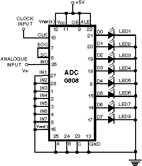
Normally analogue-to-digital converter (ADC) needs interfacing through a microprocessor to convert analogue data into digital format. This requires hardware and necessary software, resulting in increased complexity and hence the total cost. The circuit of A-to-D converter shown here is...
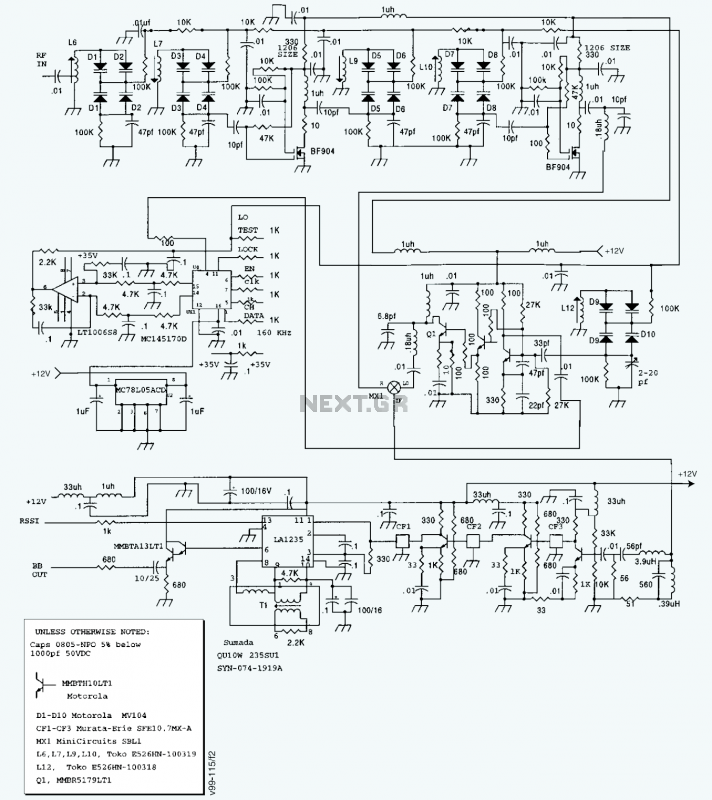
A block diagram and a schematic of the receiver are shown in Figures 2 and 3, respectively. In Figure 3, L6 and L7 are spaced 0.6 inch for a loss of about 0.5 dB. Q4 is the first RF...