
Pulsed infrared diode circuit
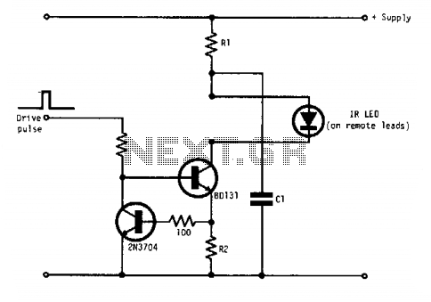
In this circuit configuration, transistors Q1 and Q2 are utilized to establish a constant current source, effectively regulating the output current based on the resistor R2. The operation of the circuit is such that when the current exceeds 1 amp, the relationship between the current and R2 can be approximated as I = 1/R2, indicating that the current is inversely proportional to the resistance value.
Capacitor C1 plays a crucial role in the circuit by providing pulse current. The charging and discharging cycles of C1 are critical for maintaining the desired output characteristics. The recharging of C1 occurs through resistor R1 during the intervals between the current pulses. The value of C1 is selected based on the specific requirements of the application, particularly the peak current magnitude and the duration for which this peak current is needed.
The time constant of the circuit, defined by the product of R1 and C1 (τ = R1C1), dictates the response time of the circuit and the duration between the pulses. A longer time constant results in a slower response, which may be suitable for applications requiring longer intervals between pulses, while a shorter time constant allows for quicker transitions, catering to applications demanding rapid pulse sequences.
This configuration is commonly applied in various electronic applications, including signal modulation, pulse width modulation (PWM) control, and other scenarios where precise current control is essential. The design ensures that the circuit can efficiently handle the specified requirements while maintaining stability and performance across a range of operating conditions.Ql and Q2 form a constant current drive defined by R2. (I approximates to the reciprocal of R2 in the circuit shown for values of I greater than 1 amp). The pulse current is drawn from Cl which is recharged during the time between pulses via Rl. The value of Cl is determined from the duration and magnitude of the peak current required, and the time constant Rl Cl is determined from the duration between pulses. 🔗 External reference
Related Circuits
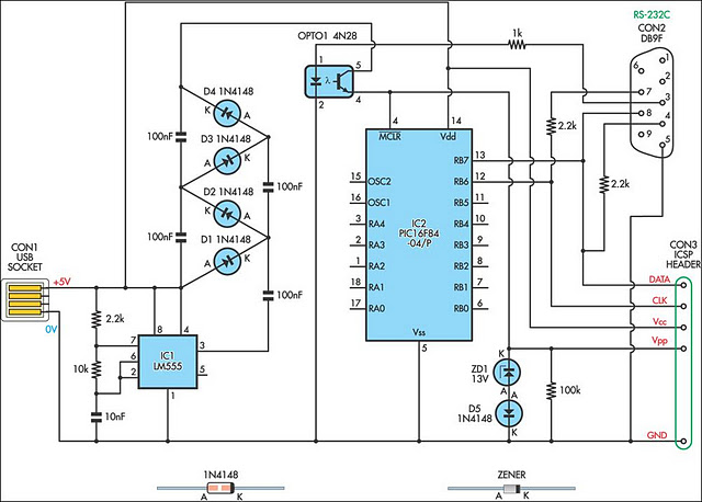
A small biped walker constructed from 2mm plywood, powered by two RC servos. It utilizes the widely available and programmable flash microcontroller PIC16F84. This simple circuit is designed to program the PIC16F84 and similar flash memory components. The project...
A simple 3-way crossover, intended for triamping Hi-Fi systems. This is a conventional 12dB / Octave unit, and cannot be expected to have the same performance as a Linkwitz-Riley aligned filter network. It will still be a vast improvement...

This design circuit is for a temperature sensor that utilizes an LM335 integrated circuit (IC) to convert ambient temperature into an equivalent output voltage. The output voltage of the LM335 increases by approximately 10 mV for every 1 degree...
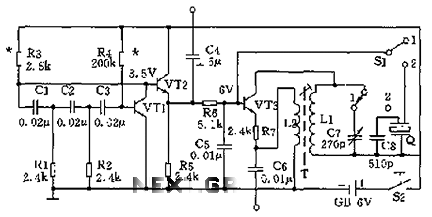
The high-frequency signal generator is designed to produce a low frequency of 1 kHz, an intermediate frequency (IF) signal of 465 kHz, and high frequencies ranging from 525 kHz to 1605 kHz. This device is particularly useful for radio...
This circuit is a motion detection sensor that utilizes a light source and a detector in the form of an infrared motion detector. The motion sensor employs an infrared LED and a phototransistor. The sensitivity of the sensor can...
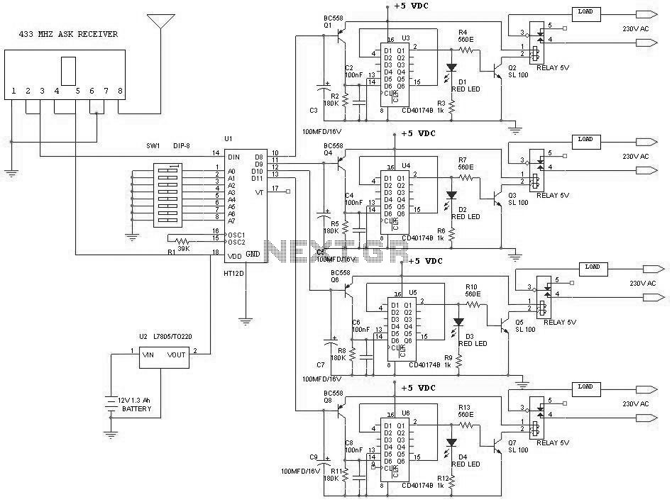
This project outlines a simple remote control system utilizing RF communication without a microcontroller. The remote is designed to operate various home appliances such as televisions, fans, and lights, providing convenience by allowing users to control devices from a...
Warning: include(partials/cookie-banner.php): Failed to open stream: Permission denied in /var/www/html/nextgr/view-circuit.php on line 713
Warning: include(): Failed opening 'partials/cookie-banner.php' for inclusion (include_path='.:/usr/share/php') in /var/www/html/nextgr/view-circuit.php on line 713