
Precision polarity switching circuit by conventional elements
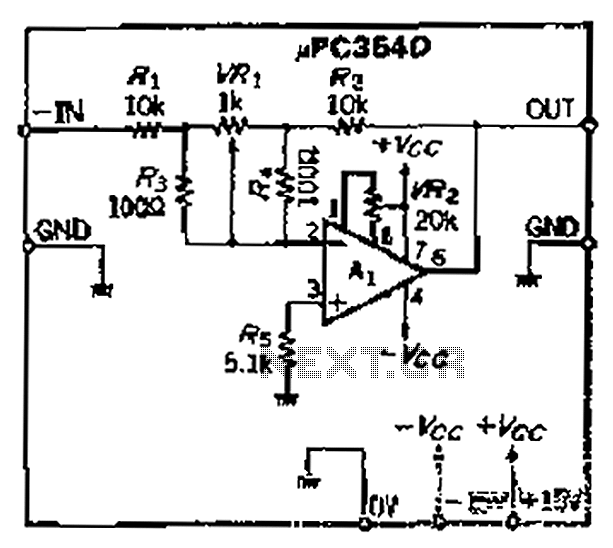
The operational amplifier circuit described focuses on maintaining accurate gain through careful selection of resistors. The loop gain is a critical parameter in determining the overall performance of the amplifier, which is affected by the ratio of the input resistor (R1) and the feedback resistor (R2). Any variation in these resistances can introduce errors in the gain, which can be detrimental to the circuit's performance.
To mitigate these errors, high-precision resistors are recommended, especially for the variable resistor (VRi), which is essential for fine-tuning the circuit's response. The design should ensure that the resistors used have a tolerance of 1% or better to maintain accuracy. In this case, R1 is specified as 9 kΩ, while R2 is set at 10.1 kΩ. The choice of these values is deliberate, as they are close to a standard value and provide a manageable range for adjustments.
The variable resistor (VRi) allows for the adjustment of the gain, and its design must accommodate the necessary precision. The gain adjustment can be fine-tuned within a narrow range, which is crucial for applications requiring high fidelity. The circuit should be laid out to minimize parasitic capacitance and inductance, which could further affect the gain stability.
In summary, the operational amplifier circuit relies on the precise ratio of resistances to ensure accurate gain. The use of high-precision resistors and careful design considerations will lead to improved performance, enabling the circuit to meet the stringent requirements of various applications. Because the loop gain of the amplifier OP depends mainly on the dry input resistor and feedback resistor ratio, so the resistance error, an error occurs opening will be a corre sponding gain in order to get more accuracy caused by four, you need high-precision resistors for o narrow range of VRI variable resistor Rs, ugly whose resistance Rl, R2 1/100, this kind of deviation can be compensated resistance, RL is actually g. 9kQ, Rz is 10.1 kQ, this worst-case scenario is very small, so VRi adjustable range of disabilities 1% is enough.
Related Circuits
This microphone circuit was submitted by Lazar Pancic from Yugoslavia. The sound card for a PC typically features a microphone input, speaker output, and occasionally line inputs and outputs. The microphone input is designed specifically for dynamic microphones with...
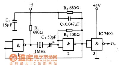
The oscillator circuit consists of a 1MHz quartz crystal resonator and a NAND gate, with the output buffer stage provided by NAND gate 3. This circuit can be utilized for calibrating standard frequency. The described oscillator circuit operates at a...
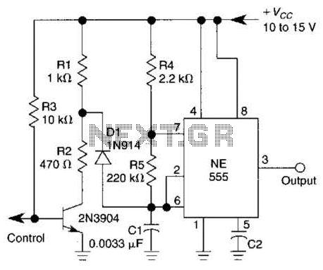
A 1-kHz gated oscillator with no long turn-on cycle is shown. R2, R3, and D1 preset the voltage on tuning capacitor C1 to a percentage of the supply voltage. The circuit described functions as a gated oscillator operating at a...

This jam circuit is designed for quiz contests, allowing participants to press their button (switch) to gain the first opportunity to answer a question. The circuit accommodates up to eight contestants, each assigned a unique number (1 to 8)....
Electronic Schematic Circuit Diagrams Manual PDF Download. The document provides a comprehensive manual that focuses on electronic schematic circuit diagrams. These diagrams are essential tools for understanding and designing electronic circuits, offering visual representations of circuit components and their interconnections....
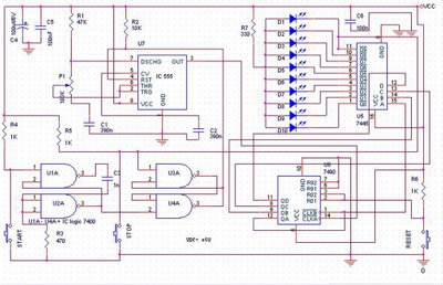
The speed test circuit is a simple design intended to measure a person's reaction time in a game. The operation of this peripheral is straightforward, facilitated by several integrated circuits, including a counter, timer IC, and decoder. The timer...
Warning: include(partials/cookie-banner.php): Failed to open stream: Permission denied in /var/www/html/nextgr/view-circuit.php on line 713
Warning: include(): Failed opening 'partials/cookie-banner.php' for inclusion (include_path='.:/usr/share/php') in /var/www/html/nextgr/view-circuit.php on line 713