
KTM03 type for single-phase half-controlled rectifier circuit

The circuit operates by utilizing an adjustment potentiometer connected to the Raspberry Pi, which allows for real-time modifications to the conduction angles of the thyristors VI and V2. This adjustment directly influences the power delivered to the DC motor M, thereby controlling its speed. The thyristors act as electronic switches that can be turned on and off at specific intervals, determined by the conduction angle, which is the duration for which they remain on during each cycle of the AC waveform.
The speed feedback mechanism is critical for maintaining the desired motor speed. It employs a tachometer generator (TG) that produces a voltage proportional to the motor's rotational speed. This voltage serves as feedback to the control system. The feedback signal is then processed through a potentiometer (RP2), which allows for fine adjustments to the feedback level. By tuning RP2, the system can be calibrated to ensure that the feedback is accurate and responsive to changes in motor speed.
This configuration establishes a closed-loop control system, where the actual speed of the motor is continuously monitored and compared to the desired speed set by the user through the potentiometer. If discrepancies arise between the desired and actual speeds, the control system automatically adjusts the conduction angles of the thyristors to correct the motor speed, ensuring stable and efficient operation. The integration of these components results in a robust and adaptable motor control solution suitable for various applications.Adjustment potentiometer RPi, can change the thyristor VI, V2 conduction angle, that is changing the DC motor M speed. Speed feedback circuit is [by tachometer generator TG and potentiometer RP2 (to adjust the amount of feedback)], in fact, is now closed loop control.
Related Circuits
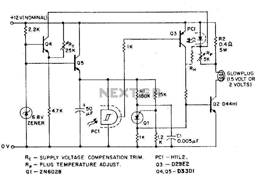
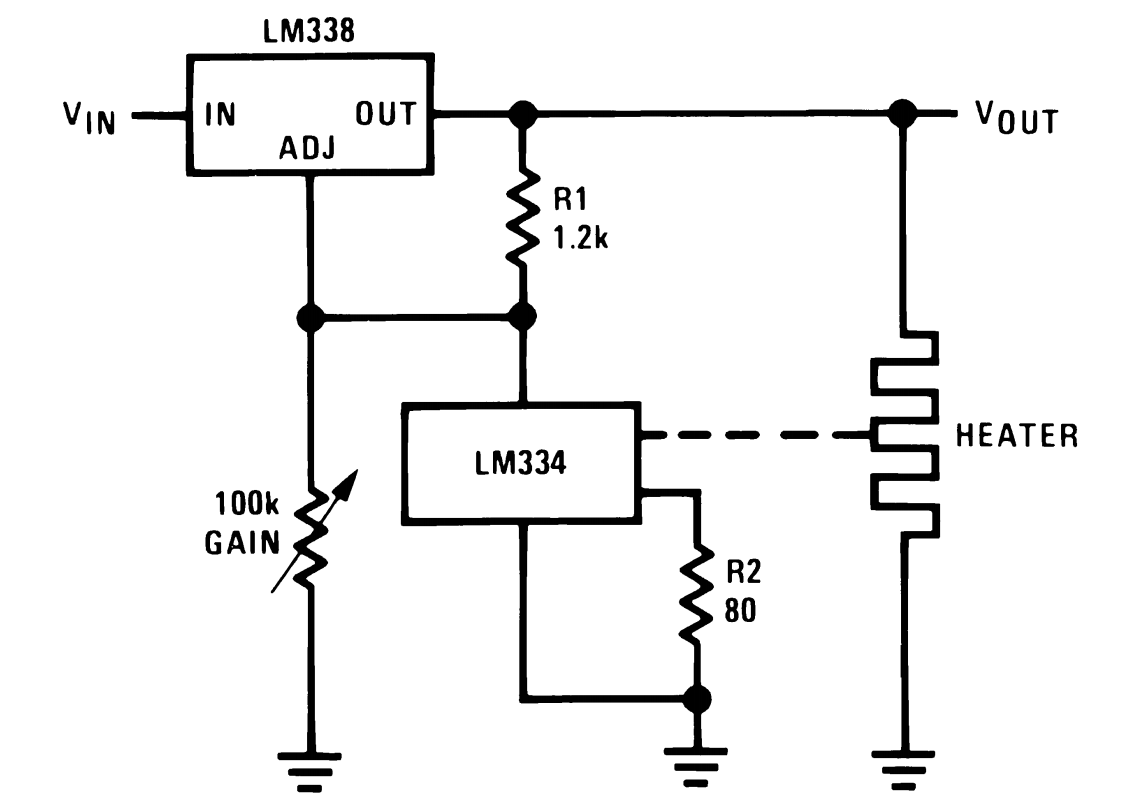
The circuit is designed for model airplanes, boats, and cars that utilize glow plugs for their miniature internal combustion engines (ranging from 0.1cc to 15cc). These engines are equipped with heavy batteries, high-tension coils, and capacitors necessary for classic...
This is a luminous flux test circuit that utilizes optical resistors. In the circuit, the optical resistor RG forms a bridge with resistors RP1, RP2, R1, and R2. RP1 is employed to balance the bridge, while RP2 is used...

The circuit is primarily composed of the integrated voice chip ISD2560. The Winbond ISD2560 is a chip with robust voice recording capabilities, featuring a permanent memory circuit for voice recording. It has a recording duration of 60 seconds and...
This is a programmable alarm timer circuit that uses LEDs to indicate hours and minutes. Twelve LEDs can be arranged in a circle to represent the 12 hours of a clock face, and an additional 12 LEDs can be...
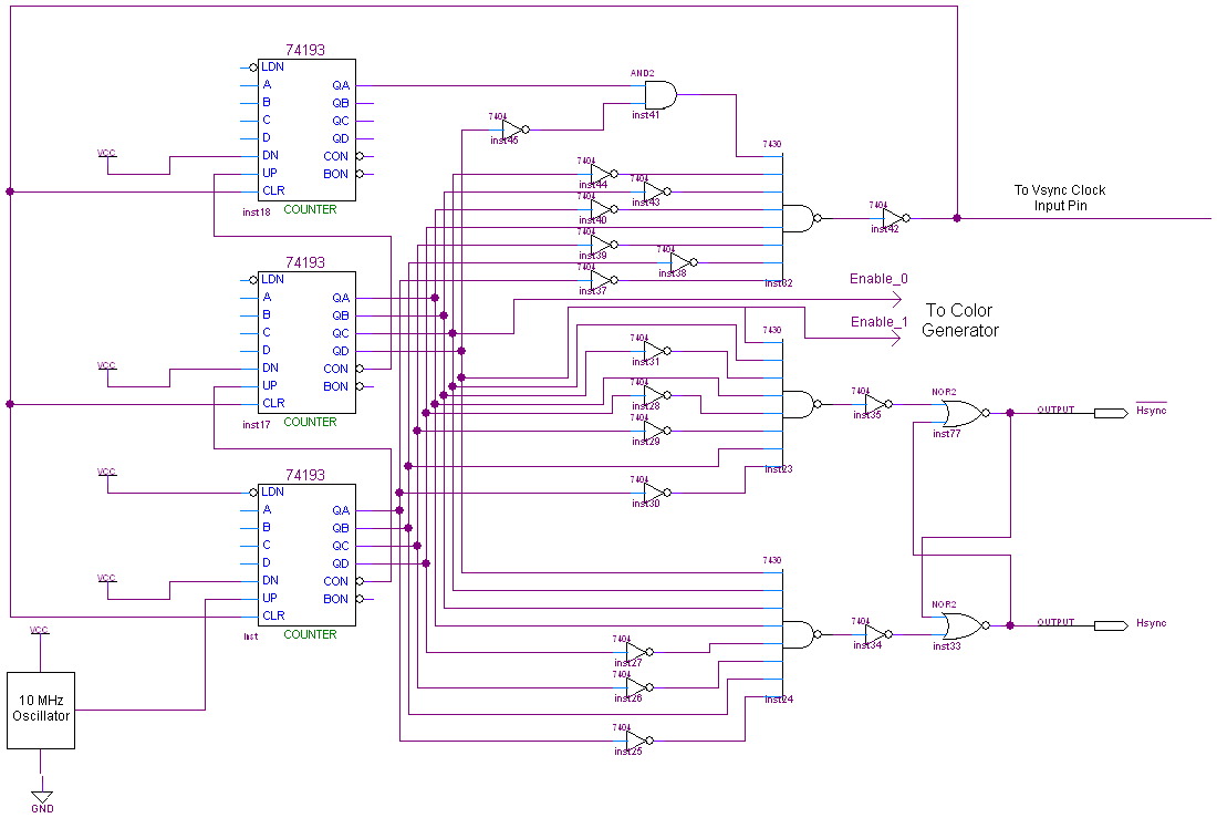
The complete schematic for this project is quite extensive. To view it, please click the image below. Due to its size, the explanation of the connections is divided into three sections: the Hsync Generator, Vsync Generator, and Color Generator....
This power supply utilizes a single 7812 IC voltage regulator along with multiple external pass transistors, enabling it to deliver output load currents of up to 30 amps. The circuit design incorporates a 7812 linear voltage regulator, which is...