
Buffer op-amp / Unity Gain Follower using LM741

The buffer op-amp circuit serves a critical role in electronic design by providing impedance matching between different stages of a circuit. By using a unity gain configuration, the op-amp outputs the same voltage that it receives at its input, while isolating the input from the output. This characteristic is particularly useful in scenarios where the source circuit has a high output impedance and the load circuit has a low input impedance.
In practical applications, the buffer op-amp circuit can be implemented using a single operational amplifier. The non-inverting input is connected to the input voltage signal, while the output is directly connected to the inverting input, creating a feedback loop that maintains unity gain. This configuration ensures that the op-amp can drive the load without affecting the source circuit's performance.
The advantages of using a buffer op-amp include improved signal integrity, reduced loading effects, and the ability to drive capacitive loads without distortion. Additionally, it can be used in various applications such as analog signal processing, sensor interfacing, and audio signal conditioning, where maintaining the original signal level is essential. Overall, the buffer op-amp circuit is a fundamental building block in modern electronic systems, enabling seamless interaction between different circuit components.The buffer op-amp circuit or Used for coupling two circuits together or the Unity Gain Follower Voltage Follower used to transfer or copy a voltage from a first.. 🔗 External reference
Related Circuits
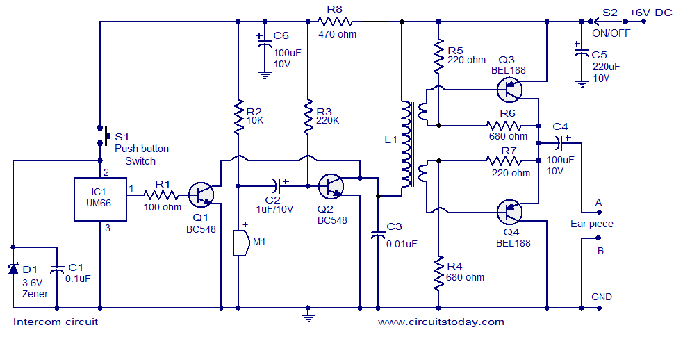
A straightforward intercom circuit designed using transistors. It does not require a changeover switch and can be used similarly to a telephone. This intercom circuit utilizes transistors to facilitate communication between two or more stations without the need for complex...

The board can now be tested. Set the DIP switch to Switch1 ON, Switch2 OFF (15-second delay), Switch3 ON, and Switch4 OFF (4 rings to activate half for switching ON). To switch ON relay 1 (connected to RB0 of...
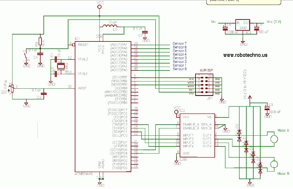
This line follower robot utilizes the following components: eight phototransistor proximity sensors, an ATMega16 microcontroller, an L298 motor driver, and is programmed using the C programming language. The line follower robot is designed to navigate along a designated path by...
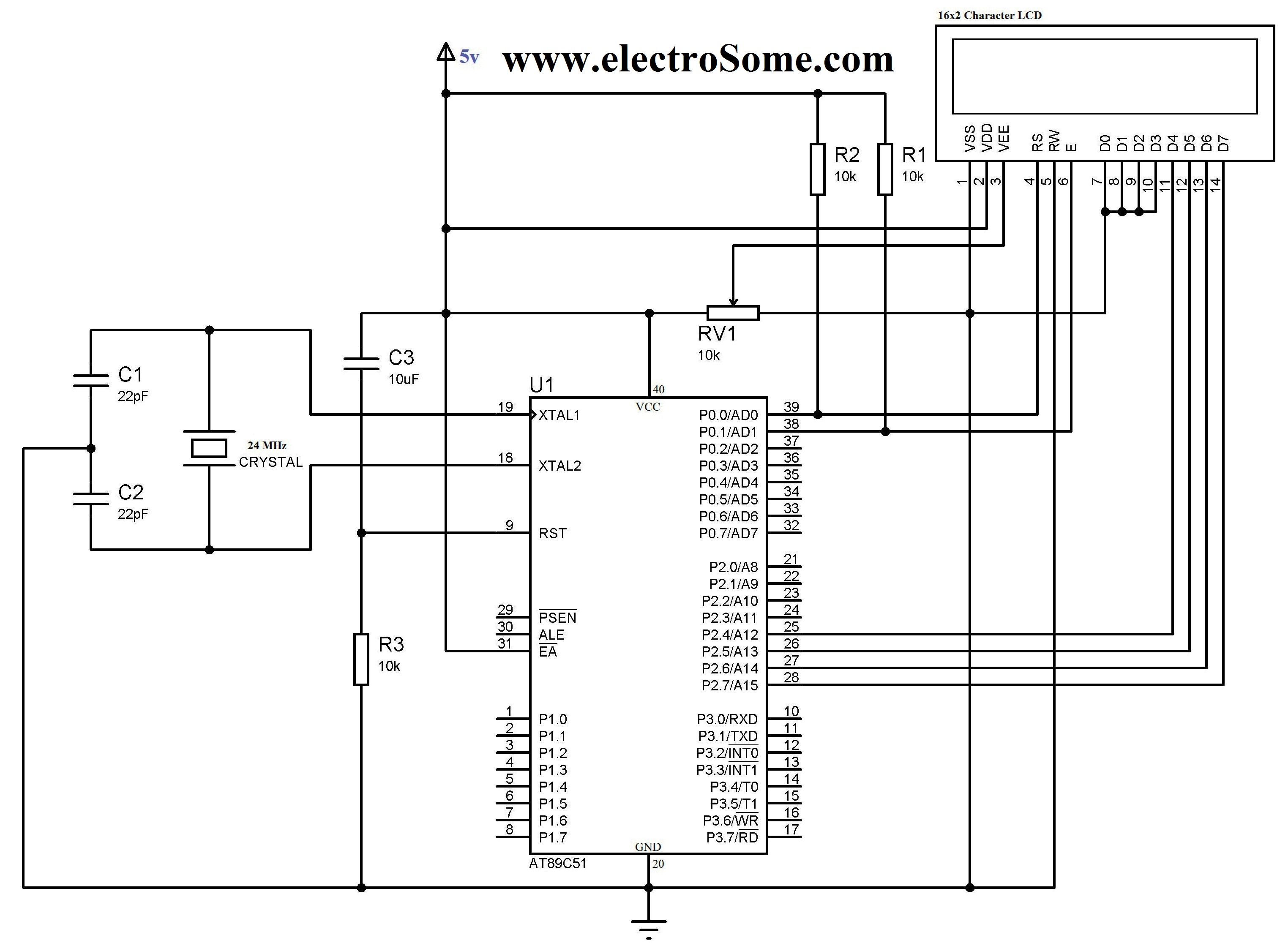
The 16x2 character LCD display is a basic module commonly utilized in electronic devices and projects. It can display 2 lines of 16 characters each. Each character is formed using a 5x7 or 5x10 pixel matrix. Interfacing the 16x2...
The project involves the creation of a line-follower robot. This microcontroller-based robot is designed to follow a black line on the ground. The line-follower robot utilizes a microcontroller as its central processing unit, which interprets input signals from various sensors...
This project is a successor to SSTC1, which has been retired. The purpose of this coil is to operate with its breakout suppressed, demonstrating the concept of wireless power that Tesla himself worked on during his time. Further videos...