
line follower tutorial based atmega16 l298 motor driver

The line follower robot is designed to navigate along a designated path by detecting and following lines on the ground. The system employs eight phototransistor proximity sensors strategically placed to enhance detection accuracy. These sensors are capable of identifying contrasts between the line color and the surface, allowing the robot to make real-time adjustments to its movement.
The heart of the robot is the ATMega16 microcontroller, which processes the input signals from the phototransistor sensors. This microcontroller is programmed in the C programming language, enabling the implementation of algorithms that determine the robot's direction based on sensor readings. The software logic typically involves comparing the values from the sensors to decide whether the robot should move forward, turn left, or turn right.
The L298 motor driver is utilized to control the motors that drive the robot's wheels. This driver can control the speed and direction of the motors based on the signals received from the ATMega16 microcontroller. It is capable of driving two DC motors, allowing for differential steering, which is essential for maneuvering the robot along curves and corners of the line.
Overall, the combination of these components allows the line follower robot to operate efficiently and reliably, making it a practical example of robotics and automation in action. The integration of sensors, microcontroller, and motor driver, along with the programming in C, showcases the fundamental principles of electronic circuit design and embedded systems.This line follower robot use the following module: Proximity sensor: 8 pcs of phototransistors; ATMega16 Microcontroller; Motor driver L298; C Programming language 🔗 External reference
Related Circuits
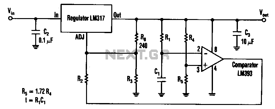
The timed two-voltage circuit can start and run a small DC motor or solenoid. The input voltage to the LM317 three-terminal regulator ranges from 5 to 40 V, and the output voltage can range from 2 to 36 V....
This is a circuit for controlling the speed of small DC motors; it works nicely as a speed controller for an HO or N gauge model railroad. More: The left half of the 556 dual timer IC is used...
Stepper motors are offered in various versions and sizes, accommodating a range of operating voltages. This general-purpose controller supports voltages from approximately 5 V to 18 V. It can drive the motor with a peak voltage equal to half...
A simple, time-honored approach is to use one or more 74AC245 chips (normally the 74AC245 is used for maximum current capability) to provide motor drive current. Here, each channel of drive power is provided by one or more buffer...

Music Driven Motor Schematic. The geared motor drives the stem of a dancing flower to the beat of music. The music-driven motor schematic involves a geared motor that is activated in response to sound signals, specifically music. This design typically...
This integrated circuit is highly efficient and does not require any external glue logic for operation. It features two pins for motor control: one pin is dedicated to controlling the direction of the motor, while the other pin is...