
Bug Eyed Eggliner

The Bug-Eyed Eggliner project is an engaging endeavor that combines creativity with electronics, resulting in a unique animated figure. The core components of the project include two large wooden balls that serve as the eyes, each equipped with a 5mm LED for illumination. The eyes are designed to be movable, achieved through a servo mechanism controlled by a PICAXE microcontroller. This microcontroller is programmed to manage the servo's operation, allowing the eyes to blink and move back and forth, thereby enhancing the visual appeal of the Eggliner.
To initiate the project, the Eggliner toy must be disassembled. This involves removing the outer screws from the base to separate the motor block from the body, ensuring that no damage occurs to the internal wiring. The interior cardboard oval, which does not have a reuse purpose, can be removed by prying or cutting it out, allowing for easier access to the internal structure.
Once the Eggliner is halved, the eyes are mounted through two 1/4" holes, which are carefully drilled into each wooden ball. The process begins with marking the center of each eye and drilling a small pilot hole with a 1/16" diameter to guide the larger 1/4" hole. This technique ensures precision and alignment. It is recommended to drill the holes vertically for optimal results, although slight angles can be adjusted to match the contour of the Eggliner's body.
Further modifications include drilling a 7/32" diameter hole at the bottom of each eye to accommodate the brass tubing, which will serve as a support structure for the servo mechanism. If the wooden balls have pre-existing holes, these can be expanded to the required diameter to facilitate the installation of the tubing.
To finalize the assembly, two 1.25" long pieces of the 7/32" brass tubing are cut and glued into place, providing a secure mount for the eyes. The integration of the PICAXE microcontroller and servo motor is essential, as it allows for dynamic movement and lighting effects, making the Bug-Eyed Eggliner not only a fun project but also an educational experience in electronics and mechanical design. This project fosters creativity and encourages experimentation with various materials and components, paving the way for further exploration in similar electronic animations.How the Bug-Eyed Eggliner came to life along with instructions that will help you to make your own. I believe that you can also use many of the concepts presented here in other projects and animations. The honey bee Eggliner already has two large eyes painted atop its body. It seemed logical to make them larger, 3 dimensional, illuminated and movable. I experimented with a number of different spheres until I found wooden balls at Michaels, a local craft store. Wood is easy to paint and to work with simple tools and the balls came in a variety of different sizes. I decided to add a single 5mm LED to the center of each eyeball and to design and build a servo based mechanism to move the eyeballs back and forth.
A PICAXE microcontroller is used to drive the servo and to blink the lights on and off. This list shows what I used to make the Bug-Eyed Eggliner. There are many substitutions that could be made if you can`t locate exactly what is shown here. Brass tubing - 12" long, 7/32" diameter - search eBay for "brass tube 7/32" - locally available at hardware stores & hobby shops - this must fit smoothly inside of the 1/4" tube described above Remove the motor block and base from the Eggliner by removing the outer four screws from the bottom (circled below). The inner screws hold the motor block to the base and do not need to be removed. Unsolder the bundle of red and black wires from the circuit board (area circled below). These wires connect the Eggliner`s interior lights to track power. We will solder them back on when we are all done. Remove the white cardboard oval that is inside of the Eggliner`s body. You can pry off the blobs of hot melt glue that hold it in place or you can cut it out. It will not be reused so damaging it during removal is not an issue. Unless you have VERY tiny hands it is easiest to work on the Eggliner once it has been split in half.
Note the thick line of hot melt glue that runs across the middle of the Eggliner joining the front and back. Pry as much of it off as you can with a flat blade screwdriver. Gently pry the two sections apart being careful not to break the interior lighting wires. The eyes will mount onto the Eggliner body through two 1/4" holes. Use a marker to place a dot in the center of each painted eyeball. Once you are satisfied that you have marked the center drill a 1/16" diameter hole through the eye. Drilling the small hole first will make it much easier to drill the 1/4" hole. While holding the drill perpendicular to the eyeball drill a 1/4" hole using the previously drilled 1/16" hole as a guide.
Note that you can drill these holes at slightly different angles to follow the contour of the Eggliner body or you can place the Eggliner body on a flat surface and drill both holes vertically. I had the best results with vertical holes. Drill a 7/32" diameter hole in the bottom of the eye. If the wooden balls you purchased have an existing hole, as mine did, just expand that hole with the drill.
Drill a bit more than 1/2 way into the ball being sure that you don`t go the whole way through. I used a drill press to expand the existing holes drilling a few intermediate sized holes before finishing up with the 7/32" hole. Cut two 1. 25" long pieces of tubing from the 7/32" brass tubing. These will be glued int 🔗 External reference
Related Circuits
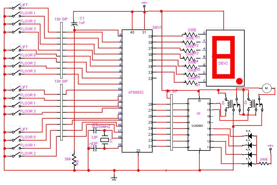
A circuit design has been conceptualized, and an Assembly code program has been drafted for a three-level mini system. The described circuit design focuses on a three-level mini system, which can be interpreted as a hierarchical structure where each level...
This is just one of the many bugging devices available on the eavesdropping market. The range includes pen and pencil holders, trophies, framed pictures, and office furniture with false bottom drawers. These products are readily sold to fledgling companies,...
A hexapod walker robot that employs three servos. It utilizes a Parallax Basic Stamp I as its control unit, which is essential for its walking functionality. The body of the hexapod is constructed from standard Radio Shack protoboard, lacking...
Today they have moved up to 900MHz. It is not easy to build stuff for 900MHz so in this project I will re-use an old cordless 900MHz phone I found in a container. Since you wont have the same...
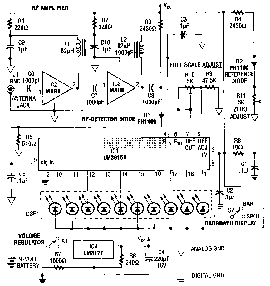
This RF detector is capable of locating low-power transmitters (such as bugs) that are not visible. It can detect the presence of a 1-mW transmitter from a distance of 20 feet, making it sensitive enough to identify even the...
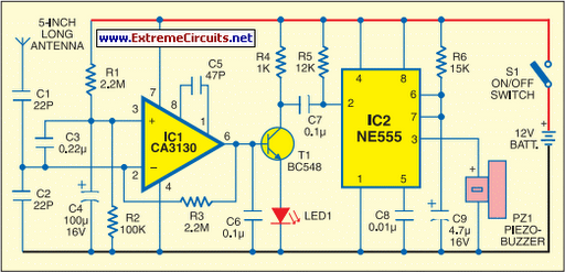
This portable mobile transmission detector can detect the presence of an activated mobile phone from a distance of 1.5 meters. It is designed to prevent the use of mobile phones in examination halls, confidential areas, and other restricted environments....