
Bug FM Transmitter

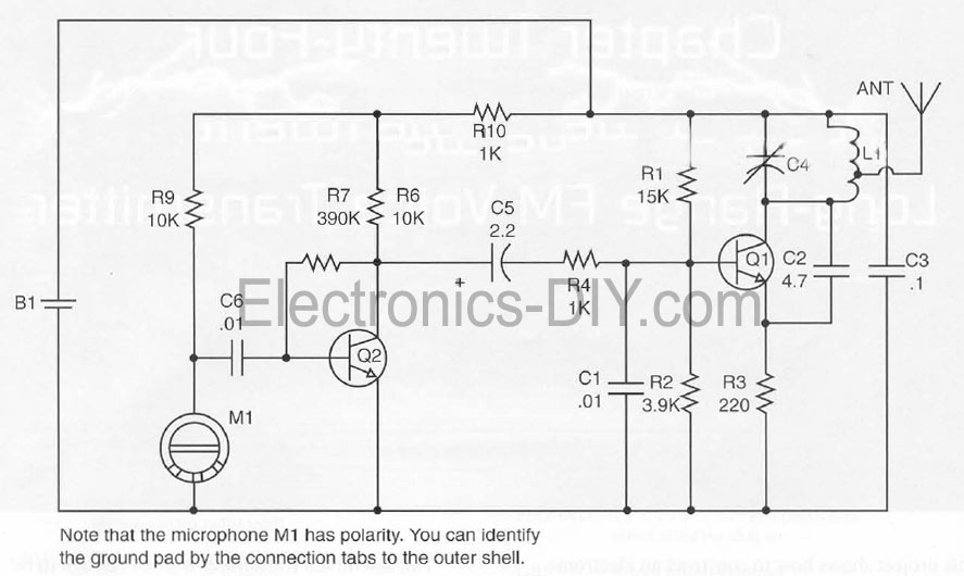
The described circuit operates as a radio frequency (RF) oscillator designed to function at approximately 100 MHz, utilizing a Colpitts oscillator configuration. The primary components include an electret microphone, two transistors, a tank circuit composed of a 5-turn coil, and a variable capacitor (trimcap). The electret microphone captures audio signals, which are amplified in the first transistor's audio amplifier stage. The amplified output from the collector of the first transistor is then routed to the base of the second transistor. This configuration allows the second transistor to modulate the resonant frequency of the tank circuit.
The tank circuit's resonant frequency is influenced by the junction capacitance of the second transistor, which varies with the potential difference applied to its base. This modulation capability is essential for the oscillator's operation, allowing it to transmit audio signals over radio frequencies. The tank circuit's design, specifically the combination of the coil and trimcap, plays a critical role in determining the frequency stability and tuning range of the oscillator.
For practical operation, the transmitter should be positioned at least 10 feet away from an FM radio set to a frequency between 89 and 90 MHz. This distance is necessary to mitigate the effects of harmonic emissions from the transmitter, which can produce signals at multiple frequencies close to the intended transmission frequency. Adjustments to the coil's winding should be made carefully, ensuring that the windings do not contact each other, and tuning of the trimcap should be performed with minimal interference from external capacitance, ideally using a plastic screwdriver.
The tuning range of the trimcap spans from 6pF to 45pF, with one complete turn covering the entire capacitance range. It is recommended to make tuning adjustments in increments of 5 to 10 degrees to optimize the frequency selection within the FM band. Experimentation with power supply voltages, such as 6V or 9V, may yield increased transmitter range, while altering the resistor value from 22K to 10K can enhance sensitivity. These adjustments allow for fine-tuning of the circuit's performance, accommodating various operational requirements.The circuit is basically a radio frequency (RF) oscillator that operates around 100 MHz. Audio picked up and amplified by the electret microphone is fed into the audio amplifier stage built around the first transistor. Output from the collector is fed into the base of the second transistor where it modulates the resonant frequency of the tank circuit (the 5 turn coil and the trimcap) by varying the junction capacitance of the transistor.
Junction capacitance is a function of the potential difference applied to the base of the transistor. The tank circuit is connected in a Colpitts oscillator circuit. Place the transmitter about 10 feet from a FM radio. Set the radio to somewhere about 89 - 90 MHz. Walk back to the Fm Tx and turn it on. Spread the winding of the coil apart by approximately 1mm from each other. No coil winding should be touching another winding. Use a small screw driver to tune the trim cap. Remove the screwdriver from the trim screw after every adjustment so the LC circuit is not affected by stray capacitance. Or use a plastic screwdriver. If you have difficulty finding the transmitting frequency then have a second person tune up and down the FM dial after every adjustment.
One full turn of the trim cap will cover its full range of capacitance from 6pF to 45pF. The normal FM band tunes in over about one tenth of the full range of the tuning cap. So it is best to adjust it in steps of 5 to 10 degrees at each turn. So tuning takes a little patience but is not difficult. The reason that there must be at least 10 ft. separation between the radio and the Tx is that the Tx emits harmonics; it does not only emit on one frequency but on several different frequencies close to each other. NOTE: You may experiment with using 6V or 9V with the circuit to see how this increases the range of the transmitter.
The sensitivity may be increased by lowering the 22K resistor to 10K. Try it and see. 🔗 External reference
Related Circuits
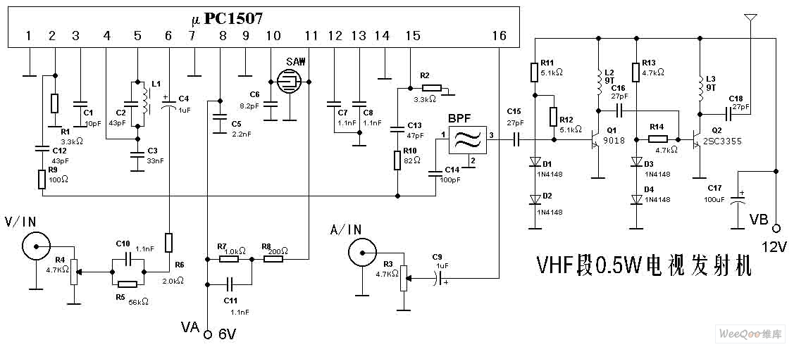
The TV transmitter described here is capable of transmitting audio and video signals from satellite television receivers, VCD players, and video recorders through an open circuit. It can also receive signals using open antennas. This device is ideal for...
Current loop analog data transmission is utilized in industrial environments due to its robustness, offering good noise immunity and the capability for wiring fault detection. Current loop analog data transmission systems are widely employed in industrial applications due to their...
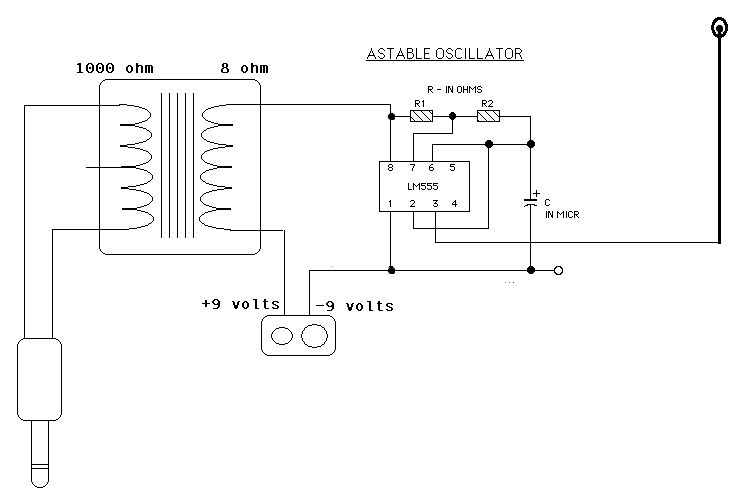
Two ICM7555 CMOS 555 timers are available, and there is an inquiry about effective AM radio transmitter circuits that utilize one or both of these timers. The ICM7555 is a low-power CMOS version of the classic 555 timer, which can...
This document presents a Long Range FM Transmitter circuit, which is a highly sensitive, low-power FM transmitter. It includes a radio frequency (RF) oscillator section connected to a high-sensitivity, wide pass-band audio amplifier and a capacitance microphone equipped with...
This fairly simple circuit makes it possible to place such a wall as a conduit to locate. It is a conduit for power, no water or gas-seeker. The only requirement is that there is tension on the line. The...

The FM transmitter is relatively simple to build and requires only one adjustment, making it ideal for beginners. It is important to clarify that, with wide-band deviation, the Voltage Controlled Oscillator (VCO) is never locked in phase, only in...